I'm making something for my airbus project, It is intended for LED lights to turn on and off and to
controll a servo. I made an app in MIT App Inventor 2. The problem is that when I turn on the LED
will also move my servos. I uploaded the servo sketch
I made a movie with what i mean
https://www.youtube.com/watch?v=SdYp4fsyI70&feature=youtu.be
The led sketch :
#include <Servo.h> // servo library
Servo gaston; // create servo object to control a servo
int poser = 90; // initial position of servo
int value; // initial value of input
void setup()
{
Serial.begin(9600); // Serial comm begin at 9600bps
gaston.attach(9);// server is connected at pin 9
}
void loop()
{
while(Serial.available()) //read while data is present
{
value = Serial.read(); //value = serial read data from phone
poser = value ; //than position of servo motor equals to value of data read from phone
gaston.write(poser);// the servo will move according to position
delay(15); }
}
controll a servo. I made an app in MIT App Inventor 2. The problem is that when I turn on the LED
will also move my servos. I uploaded the servo sketch
I made a movie with what i mean
https://www.youtube.com/watch?v=SdYp4fsyI70&feature=youtu.be
my english is so good, especially if we talk technical :s
The led sketch :
int ledpin = 5;
String readString;
void setup() {
Serial.begin(9600);
pinMode(ledpin, OUTPUT);
}
void loop() {
while (Serial.available()) {
delay(3);
char c = Serial.read();
readString += c;
}
if (readString.length() >0) {
Serial.println(readString);
if (readString == "a")
{
digitalWrite(ledpin, HIGH);
}
if (readString == "b")
{
digitalWrite(ledpin, LOW);
}
readString="";
}
}
The servo sketch :
#include <Servo.h> // servo library
Servo gaston; // create servo object to control a servo
int poser = 90; // initial position of servo
int value; // initial value of input
void setup()
{
Serial.begin(9600); // Serial comm begin at 9600bps
gaston.attach(9);// server is connected at pin 9
}
void loop()
{
while(Serial.available()) //read while data is present
{
value = Serial.read(); //value = serial read data from phone
poser = value ; //than position of servo motor equals to value of data read from phone
gaston.write(poser);// the servo will move according to position
delay(15); }
}
someone was talking about "The Servo sketch will react to the LED commands sent from App Inventor because Serial.read() will return the values 79 and 110 - the ASCII codes for "On".
but not have a solution.
does anyone know this?
I can not find on the Internet that they work separately from each other,
there is something they both respond to, perhaps from app inventor.
I appreciate it if someone knows a solution
there is something they both respond to, perhaps from app inventor.
I appreciate it if someone knows a solution
--
You win the prize for shakiest screen shot.
Could you do an AI2 Download Blocks as Image and post it to your thread?
(seasick)
--
haha Thanks for the reward, Would indeed be useful a image, thanks for te reminder

--
This is the first time I've seen two devices connected to the same AI2 BlueTooth Client at the same time.
You are sending a text "a" (ascii 97) or the slider value as a byte value from AI2.
How does the receiving side know the difference between a byte of 97 and a text "a" ?
(See the Ascii table)
--
I do not know what you mean Abraham, It is very difficult for me, I did not know much about it. its 1 devices thats connected to the BlueTooth Client, not two
I do not know How the receiving side know the difference between a byte of 97 and a text "a" i have also need to merge the sketchs. What I can not.
I need two sketchs to work with A12 one for the slider to turn the servo and one or more buttons for led to turn on and off.
--
It seems to me that if you want to control 2 devices from one phone, you should have 2 Bluetooth clients.
I tried this with one BLE and one BT device, and that worked fine. (It was a BLE motion sensor, controlling a robot-car via the phone).
I see no reason why you could not have 2 Bluetooth clients in you app.
I tried this with one BLE and one BT device, and that worked fine. (It was a BLE motion sensor, controlling a robot-car via the phone).
I see no reason why you could not have 2 Bluetooth clients in you app.
--
do you have somewhere an example? and how does the Arduino see it in the sketch
--
Please provide more detail about your hardware setup. I looked at your video, but it was not clear to me.
You say you have two sketches, so I assume you have two Arduino's??
And, do they both have BT connection capabilities?
If yes, I can make an example. If no, please explain what your setup is.
You say you have two sketches, so I assume you have two Arduino's??
And, do they both have BT connection capabilities?
If yes, I can make an example. If no, please explain what your setup is.
--
I think I understand the problem.
You have several different devices you want to address on one connection from the AI2 app.
You need a text message format coming from AI2 that will contain information about
which device it wants to control and what level to use controlling it.
If you devote the first letter of the AI2 text message to the device, and subsequent letters to the text value to use,
you can do it on the hardware side by first checking the first letter =="a" or "b" for LED control or "c" for servo control.
That would involve an if/then/elseif tree on the C side.
But you will need a way to pick out what follows the "c" in the AI2 message, to feed the servo.
That would involve some C (C++?) function that might go by the name of mid() or substr()
or segment()... ((My C and C++ are very week.)
--
Yes, but...
You cannot have one connection to 2 devices simultaneously. In old BT you must disconnect and reconnect. Therefore I proposed to have two connections, and you could send a message to either, as needed. My problem is that I need to know that there are indeed 2 BT shields, like HC-05 or HC-06 or a board with built-in BT.
You cannot have one connection to 2 devices simultaneously. In old BT you must disconnect and reconnect. Therefore I proposed to have two connections, and you could send a message to either, as needed. My problem is that I need to know that there are indeed 2 BT shields, like HC-05 or HC-06 or a board with built-in BT.
--
Thanks for thinking with me Abraham and Ghica,
Maybe you have another idea, thanks
I'm going to do it differently, its to complicated for me. But I will explain it again what I wanted.
i got one arduino pro mini,
i got one hc-05,
i got one servo,
i got one LED to turn on and to turn off
i got 2 sketchs, i can only use 1 because I can not combine 2 sketchs.
If it connected to the bluetooth through AI2 and sweep my slider, my servo sweeps oke, But when I hit the button to turn on the LED, my servo sweeps ---> That's my problem....... also to combine sketchs, really hard.
i go to use now 2 arduino's, 2 hc-05, 2 sketchs,
one arduino to control all the lights, 4 to turn on and off, and 3 leds to blink. its all for a rc airbus 320, cockpit light, head lights, blinking tall lights etc. etc.
and
one arduino to control de servos to open doors and loading doors of my plane
Maybe you have another idea, thanks
--
Abraham has already given you a solution:
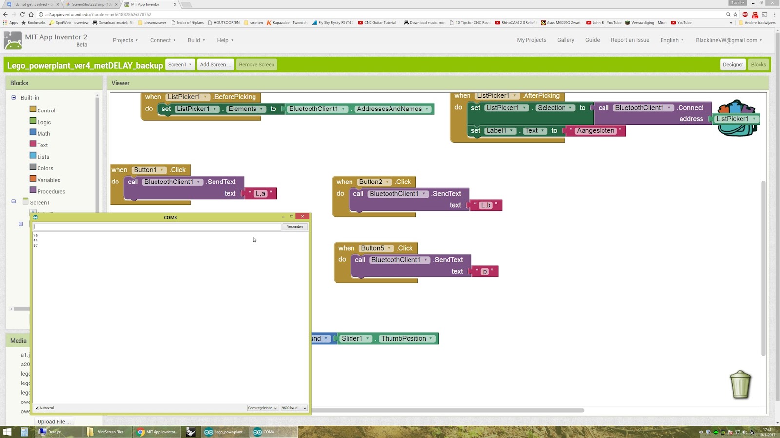
In AppInventor, Include a command indicator at the start of your Bluteooth transmission so that you can distinguish between switching on or off the LED and the movement of the servo.
so the command strings could be: " L,a" to turn on the LED; "L,b" to turn off the LED and "S,'value'", where 'value' is the slider position, to move the servo.
then, in the Arduino sketch all you need to do is read the incoming string from the Bluetooth and look for the" L," or "S," and then act accordingly
--
Looking at this, I think Abraham is right. If you would go the 2 Arduino course, in no time you will have 10 Arduino's, one for each servo, led, or whatever.
So it is much better to bite the bullet and learn some C to combine the sketches. There are many examples on the web you can find.
I have a robot car with one Arduino, 3 LED's, wheels, a servo head etc. The sketch roughly looks like this:
void loop()
{
//Receives commands from remote computer:
if (serial.available())
{
int inByte = serial.read();
//serial.println((char)inByte);
switch ((char)inByte)
{
//Actions:
case 'w':
sparki.moveForward();
break;
case 'd':
sparki.moveRight();
break;
...
// RGB
case 'i':
sparki.RGB(RGB_OFF);
break;
case 'j':
sparki.RGB(RGB_RED);
break;
case 'k':
sparki.RGB(RGB_GREEN);
break;
case 'l':
sparki.RGB(RGB_BLUE);
break;
// Servo
case 't':
sparki.servo(SERVO_LEFT);
break;
case 'n':
sparki.servo(SERVO_CENTER);
break;
case 'o':
sparki.servo(SERVO_RIGHT);
break;
//Sensor readings:
case 'r':
serial.println("<r>");
serial.print("<p>");
serial.print(sparki.ping());
serial.println("</p>");
...
}
}
--
Thank you Neil and Ghica, I am going to try with what you saying.
I'll keep you informed.....
--
A question, command strings could be: " L,a" to turn on the LED; "L,b" to turn off the LED and "S,'value'"

like this
--
That's the general idea.
Now you need to create a command string to carry the value of your slider.
Good luck
--
In fact, if you look here: https://www.element14.com/community/people/neilk/blog/2014/09/05/app-inventor-bluetooth-and-arduino-part-3-android-slider-controls-led-brightness
You will find some useful information about AI2 sliders etc.
--
@Neil: Very nice tutorial!
@Abraham: I think you should add it to your FAQ
@Abraham: I think you should add it to your FAQ
--
@Ghica - thanks!
--
yes @Neil: Very nice tutorial! Impressive,


AI2 He always sends back numbers even i give a case 'L,a': i get
also the led not turn on,
if i try case 'p': i get back
With the case 'p' command the led turn on.
I'm trying my best
this is now my led sketch :
const int pin2 = 2;
const int pin3 = 3;
const int pin4 = 4;
const int pin5 = 5;
const int pin6 = 6;
const int pin7 = 7;
const int pin8 = 8;
const int pin9 = 9;
const int pin10 = 10;
const int pin11 = 11;
const int pin12 = 12;
byte serialA;
void setup()
{
// initialize the serial communication:
Serial.begin(9600); //baud rate - make sure it matches that of the module you got:
// initialize the ledPin as an output:
pinMode(pin2, OUTPUT);
pinMode(pin3, OUTPUT);
pinMode(pin4, OUTPUT);
pinMode(pin5, OUTPUT);
pinMode(pin6, OUTPUT);
pinMode(pin7, OUTPUT);
pinMode(pin8, OUTPUT);
pinMode(pin9, OUTPUT);
pinMode(pin10, OUTPUT);
pinMode(pin11, OUTPUT);
pinMode(pin12, OUTPUT);
}
void loop()
{
if (Serial.available() > 0) {serialA = Serial.read();Serial.println(serialA);}
switch (serialA) {
case 1:
digitalWrite(pin2, HIGH);
break;
case 2:
digitalWrite(pin2, LOW);
break;
case 3:
digitalWrite(pin3, HIGH);
break;
case 4:
digitalWrite(pin3, LOW);
break;
case 5:
digitalWrite(pin4, HIGH);
break;
case 6:
digitalWrite(pin4, LOW);
break;
case 'L,a':
digitalWrite(pin5, HIGH);
delay(100);
digitalWrite(pin5, LOW);
delay(100);
break;
case 'L,b':
digitalWrite(pin5, LOW);
break;
case 9:
digitalWrite(pin6, HIGH);
break;
case 10:
digitalWrite(pin6, LOW);
break;
case 'o':
digitalWrite(pin7, HIGH);
break;
case 'p':
digitalWrite(pin7, LOW);
break;
case 13:
digitalWrite(pin8, HIGH);
break;
case 14:
digitalWrite(pin8, LOW);
break;
case 15:
digitalWrite(pin9, HIGH);
break;
case 16:
digitalWrite(pin9, LOW);
break;
case 17:
digitalWrite(pin10, HIGH);
break;
case 18:
digitalWrite(pin10, LOW);
break;
case 19:
digitalWrite(pin11, HIGH);
break;
case 20:
digitalWrite(pin11, LOW);
break;
case 21:
digitalWrite(pin12, HIGH);
break;
break;
}
}
i also need to merg it with a servo sketch
--
The slider tutorial includes only a single function in its data stream?
Does any one have an example with letters and numbers being detected and separated
on the Arduino end?
I would like to post a more general solution, which is what this post requires.
--
If you scroll down through the comments you will find an example sending red green blue slider values to arduino.
It's painful to read.
I hope Arduino type conversion and csv support improve.
AI2 has spoiled me.
--
Is this what i am looking for?
#3
Mar 22, 2013, 10:50 pm Last Edit: Mar 23, 2013, 01:20 am by HazardsMind Reason: 1
I would use 2 map functions, one for the servo and the other for the LED. Don't use the same variable for the output of the maps.
Try this
Code: [Select]
void loop() {
   val = analogRead(potpin);
  int LED = map(val, 0, 1024, 0, 255);
  int SERVO = map(val, 0, 1024, 0, 179);
  myservo.write(SERVO);
  analogWrite(ledpin,LED);
  delay(20);
}
Try this
댓글 없음:
댓글 쓰기