LinkIt ONE
Introduction
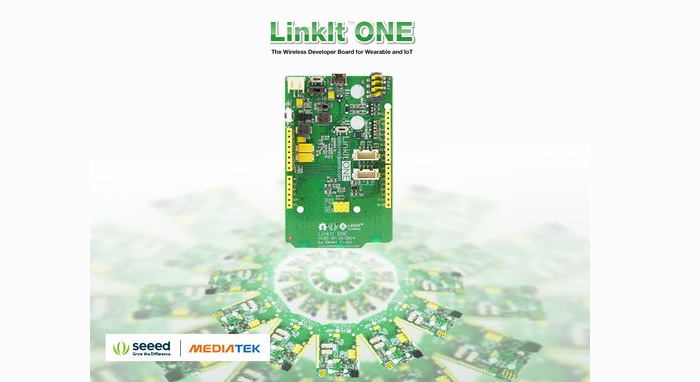
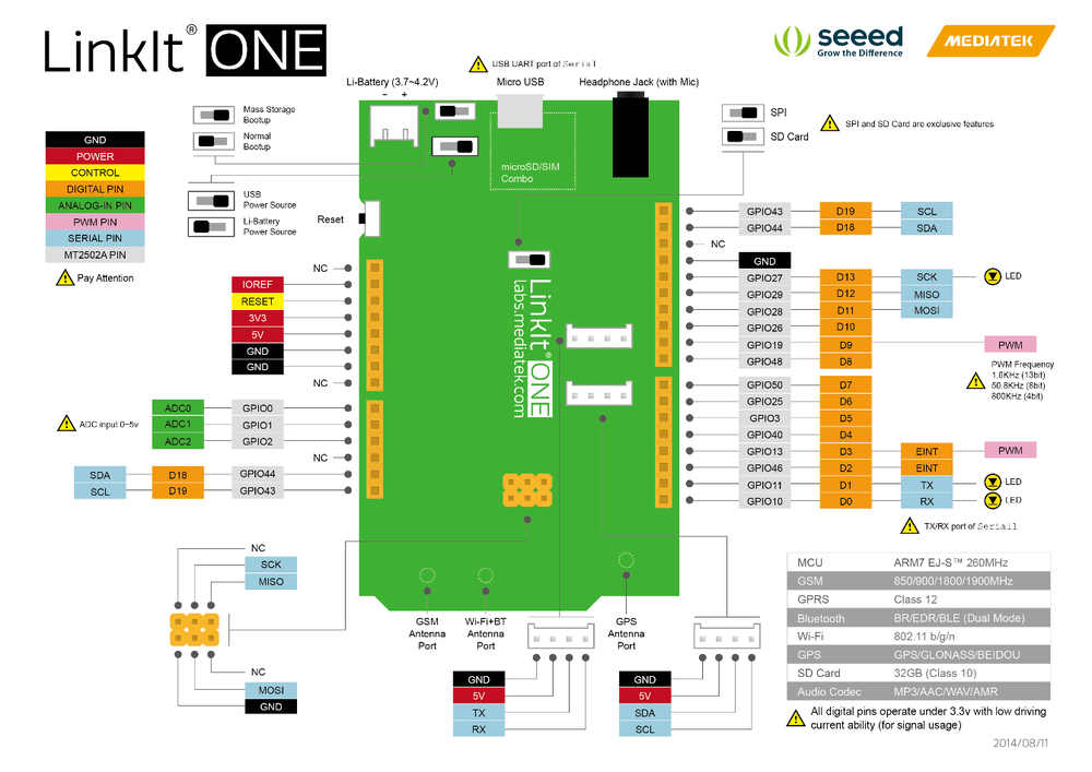
The LinkIt ONE development platform is an open source, high performance board for prototyping Wearables and IoT devices. It is based on the world’s leading SoC for Wearables, MediaTek Aster (MT2502) combined with high performance Wi-Fi (MT5931) and GPS (MT3332) chipsets to provide you with access to all the features of MediaTek LinkIt. It also provides similar pin-out features to Arduino boards, making it easy to connect various sensors, peripherals, and Arduino shields.
LinkIt One is an all-in-one prototyping board for IoT/wearables devices. Integrating GSM, GPRS, Wi-Fi, GPS, Bluetooth features into a basic Arduino form factor.LinkIt ONE is a co-design product by Seeed Studio and MediaTek. It brings together both parties’ technology in open hardware and industrial leading reference designs for Wearables and IoT devices to create a powerful development board.

Note
LinkIt ONE board comes with a lot of features and its SDK(Software Development Kit) is quite comprehensive. Read this document throughly once before using the board. Being a co-design product basic level Technical Support for hardware is provided at Seeedstudio LinkIt One Forum.Advanced Technical support is available at MediaTek LinkIt One Forums.These forums have a good number of FAQs about this board.Please search solutions for your requirements/issues first before posting questions for saving your time.
Features
- Includes ARM7 EJ-S™, GSM, GPRS, Wi-Fi, Bluetooth BR/EDR/BLE, GPS, Audio codec, and SD card connector on a single development board.
- Pin-out similar to Arduino boards, including Digital I/O, Analog I/O, PWM, I2C, SPI, UART and power supply, compatible with Arduino.
- Provides various interfaces for connecting to most sensors, peripherals, Groves, and other widgets.
- You are what you wear. Using LinkIt ONE together with MediaTek LinkIt SDK (for Arduino) you will be able to easily turn your ideas into practical prototypes and make them a reality with the Seeed productization and agile manufacturing service.
specifications
| Parameter | Value |
|---|---|
| Chipset | MT2502A (Aster, ARM7 EJ-S (TM) ) |
| Clock Speed | 260MHz |
| Dimensions | 3.3x2.1 inches |
| Flash | 16MB |
| RAM | 4MB |
| DC Current Per I/O Pin | 1mA |
| Analog Pins | 3 |
| Digital Output | 3.3V |
| Analog Input | 5V |
| UART | Software based(Serial) ,also known as USB Modem Port and Hardware Serial(Serial1, D0&D1) |
| SD Card | Up to 32GB(Class 10) |
| Positioning | GPS(MT3332) |
| GSM | 850/900/1800/1900 MHz |
| GPRS | Class 12 |
| Wi-Fi | 802.11 b/g/n |
| Bluetooth | BR/EDR/BLE(Dual Mode) |
Application Ideas
- Internet of Things
- Smart House
- Wearable Designe
- Industrial
- Sensor Hub
- Automation & Transportation
Here are some projects for your reference. More awesome project at Recipe and Instructables.
| Facebook Like Monitor | Texting Door Alarm | Smart Bed Alarm |
|---|---|---|
 |  |  |
| Make it NOW! | Make it NOW! | Make it NOW! |
| AWS IoT Tutorial | Instructables Indicator | DIY an Acrylic Case |
|---|---|---|
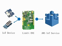 |  | 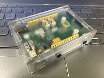 |
| Make it NOW! | Make it NOW! | Make it NOW! |
Hardware Overview
Configuration Switches
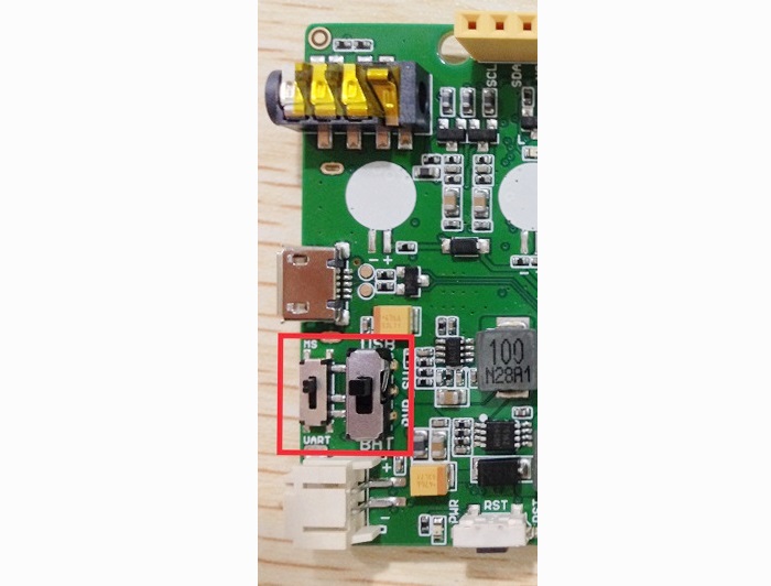
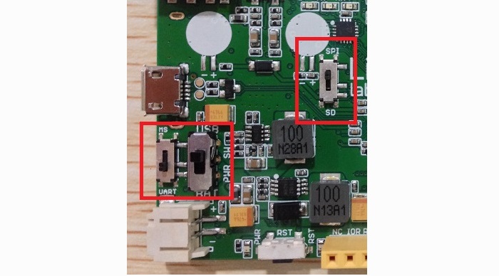
There are 3 slide switches on LinkIt ONE which are used to configure the function/working mode :
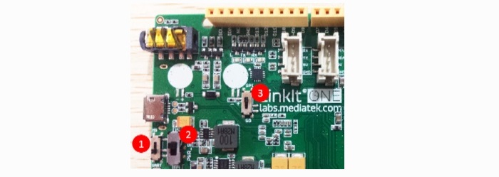
| Switch No. | Functionality | Position 1 - Functionality | Position 2 - Functionality |
|---|---|---|---|
| 1 | Program Mode | MS: In this position, when connected to PC, LinkIt One board will be shown as 10MB USB drive. The program will not execute in this mode. Any file that is copied to this drive can be read via the code. | UART:This position is used to set the board to program mode. Firmware can be uploaded in this mode. |
| 2 | Power | BAT: Board powered by Li-ion Battery. To charge battery, set the switch to this position and connect the board to PC. | USB:Board powered by USB port. Set the switch to this position when there is no battery connected to program the board. |
| 3 | SD/SPI | SPI:This position allows access of external SPI pins (D10 - D13) | SD:This position allows the code to access SD card. This mode also disables access of SPI pins (D10-D13). |
Note
DO take care as you handle USB micro type-B socket, or you might break the socket off.
Getting started
Procedure Overview
| No. | Step | Read more |
|---|---|---|
| 1 | Install Arduino IDE 1.5.7 Beta (Windows or MAC OS X version) | here |
| 2 | Register on MediaTek Labs. | |
| 3 | Download Linkit Developer’s Guide and read. | |
| 4 | Install LinkIt SDK for Arduino IDE (Windows or MAC OS X). | here |
| 5 | Install LinkIt ONE drivers. | here |
| 6 | Update the on-board firmware version. | here |
| 7 | Open Arduino IDE, Select LinkIt ONE board and start coding. | here |
| 8 | Connect GSM, GPS and WiFi/BT antennae to LinkIt One board | here |
| 9 | Insert SIM and Micro SD Card | here |
| 10 | Explore examples and Happy making! |
Installing Arduino IDE
Download latest Arduino IDE .For more advanced topics, follow MediaTekTM instructions.
Installing Mediatek LinkIt ONE SDK
- Download LinkIt SDK for Arduin.At the time of writing this guide, v1.1.11 Windows SDK (Beta) was used. Read the video guide for Windows OS and MAC OS X platforms here
- Extract the downloaded files to Arduino IDE folder.
- Double-Click the .EXE file and install.
- With the installation of LinkIt ONE SDK, Arduino IDE works a LinkIt ONE IDE.
Installing Drivers
- Disable Driver Signature Enforcement if you are using Windows 8/8.1 OS. Read[instructions]
(http://www.seeedstudio.com/wiki/Download_Arduino_and_install_Arduino_driver#Installing_drivers_for_the_Seeeduino_with_window8)
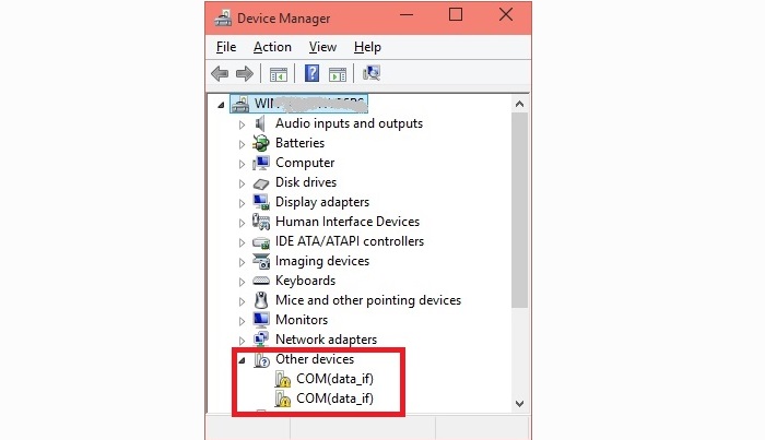
- Put the MS/UART slide switch to UART position and connect LinkIt ONE to PC.
- Open Device Manager, the following COM ports will be displayed.
- Install driver from ..\LinkIt_ONE_IDE\drivers\mtk folder.
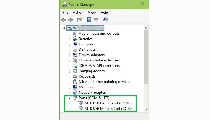
- After installing drivers, Device Manger should display the following two ports:
MTK USB Debug Port used for uploading code.
MTK USB Modem Port used for printing message, such as Serial.println()
Note
There is no official Windows 10 driver yet. Windows 10 users can manually select the Windows 7 driver files from \LinkIt_ONE_IDE\drivers\mtk from Device Manager. This is known to work on few PCs.
Updating Firmware
The firmware of LinkIt ONE board needs to be updated once in a while. Latest LinkIt ONE SDK comes with a version of firmware.
- Before starting the firmware update, make sure the slide switches are in proper position ( MS/UART should be in MS position. USB/BAT in USB position):
- Run FirmwareUpdater.exe application from ..\LinkIt_ONE_IDE\hardware\tools\mtk folder.

- Click the button and then connect LinkIt ONE to PC. Wait for 1 minutes for the update to complete successfully.

Uploading Code (Blinky)
- The slide switches should be configured for firmware upload (i.e Put MS/UART in UART position and Power switch in USB position).
- Open File -> Examples -> Basics -> Blink in LinkIt ONE IDE.
- Select the COM Port number corresponding to MTK USB Debug port in Tools -> Port.
- Compile and upload the code.
- LED marked L should blink.
Connecting Antennae
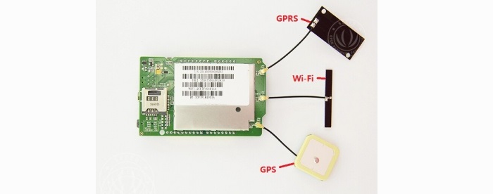
There are three antennae provided with LinkIt ONE. They are used for:
- GSM/GPRS
- Wi-Fi/BT
- GPS
Connect the antenna as the following image.
Note
- While pulling the antenna from board, do it with care. Please Do not use brute force.
- Try to use the force perpendicular to the direction of the board, otherwise you might damage the antenna pad.
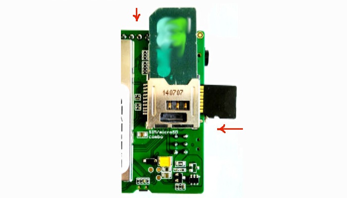
Inserting SIM Card and SD Card
LinkIt ONE accepts standard size SIM Card and Micro SD Card. Insert them as per the following image:
Exploring LinkIt ONE SDK Examples
LinkIt ONE SDK comes with many examples / sample code to use peripherals like GSM, GPRS, WiFi, BT, Audio, GPS etc. Explore them first and read about API documentation. API documentation are available in User Guide and API References site
Compatible Groves and Shields for LinkIt ONE
- We manufacture hundreds of Groves and Shields, including sensors, actuators, displays and other modules.
- You can implement your ideas with those Groves and Shields easily.
- But, LinkIt ONE does not support all of them.
- We prepared a list of compatible Groves and Shields:

Tutorial of Sidekick Basic Kit for LinkIt ONE

The Sidekick Basic Kit for LinkIt ONE is designed to be used with your LinkIt ONE board. This kit will help you quickly get along well with the platform of LinkIt. It includes many of the most popular accessories for DIY projects : like Breadboard, Jumper wires, Color LEDs, Resistors, Buzzer, etc. All these come in a handy box, which is easy to transport and mimimises clutter. The kit includes a complete guide that will familiarize you with a wide range of electronic components while you create small, simple, and easy-to-assemble circuits. There are 10 different courses outlined that will offer a best way for beginner to get familiar with LinkIt ONE.
- The Basics
- Hello World
- Push Button
- Marquee
- Colorful World
- Analog Interface
- Mini Servo
- Light Sensor
- SMS Control the LED
Resources
Schematic / Design Files:
Software:
Datasheets and User Guides:
- LinkIt_ONE_Hardware_Reference_Design_v1_0
- LinkIt ONE_Pinout Diagram_v1.0【PDF】
- MediaTek_LinkIt_Developers_Guide_v1_0【PDF】
- MediaTek_MT2502A_SOC_Data_Sheet_v1_0【PDF】
- MediaTek_MT5931_Wi-Fi_Data_Sheet_v1_0【PDF】
- MediaTek_MT3332_GPS_Data_Sheet_v1_0【PDF】
Getting Help
More
Help us make it better
Thank you for choosing Seeed. A couple of months ago we initiated a project to improve our documentation system. What you are looking at now is the first edition of the new documentation system. Comparing to the old one, here is the progresses that we made:
- Replaced the old documentation system with a new one that was developed from Mkdocs, a more widely used and cooler tool to develop documentation system.
- Integrated the documentation system with our official website, now you can go to Bazaar and other section like Forum and Community more conveniently.
- Reviewed and rewrote documents for hundreds of products for the system’s first edition, and will continue migrate documents from old wiki to the new one.
An easy-to-use instruction is as important as the product itself. We are expecting this new system will improve your experience when using Seeed’s products. However since this is the first edition, there are still many things need to improve, if you have any suggestions or findings, you are most welcome to submit the amended version as our contributor or give us suggestions in the survey below, Please don’t forget to leave your email address so that we can reply.
Happy hacking