Seeeduino Mega
Introduction

Seeeduino Mega is a powerful micro-controller derived from Arduino Mega. It features ATmega2560 processor which brings a large number of I/O pins, as much as 70 digital I/O, 16 analog inputs, 14 PWM, and 4 hardware serial ports. Compared to Arduino Mega, we shrunk the volume of Arduino Mega by at least 30% and made it 100% compatible with Seeed Shield products. And as a member of Seeeduino series, Seeeduino Mega inherits deliberate details from Seeeduino, like selectable operating voltage(3.3V/5V), right angle reset button, and so on.
Application Ideas
- Internet of Things
- DIY
- Robot
- Smart House
- 3D Printer
- Industrial
Here are some funny projects for your reference.
| 888 LED Cube | Hexapod Robot | DIY Arduino 3D Printer |
|---|---|---|
 |  |  |
| Make it Now | Make it Now | Make it Now |
Features
- Compatible with most Arduino Duemilanove and Diecimila Shields
- ATmega 2560 @ 16MHz
- Selectable 5V/3.3V operation
- 70 Digital IO
- 16 Analog inputs
- 14 PWM outputs
- 4 Hardware serial ports (UART)
- Small form factor, 30% smaller than Arduino Mega
- Easy to program, no additional hardware is required to load firmware – just plug to a USB port and you’re good to go.
- ICSP Header
- Can be powered through a battery or through a AC to DC adaptor
Specification
| Item | Value |
|---|---|
| Microcontroller | ATmega2560 |
| Operating Voltage | 5V/3.3V |
| Input Voltage | 7-12V |
| Digital I/O Pins | 70 |
| PWM Channels | 14 |
| Analog Input Channels | 16 |
| DC Current per I/O Pin | 20 mA |
| Flash Memory | 256 KB |
| RAM | 8 KB |
| EEPROM | 4 KB |
| Clock Speed | 16 MHz |
Hardware Overview
The image below shows an overview of Seeeduino Mega hardware features. The pin-out and alternate functions of various pins of Seeeduino Mega are shown in the pin-out diagram. This could be used as a quick reference.

- Mini USB Mini USB Port is used to connect the board to your PC for programming and for powering up.
- Mode Switch Slide switch used to allow or avoid automatic reset and upload.
- Power Switch Slide switch used to change the logic level and power output of the board to either 5V or 3.3V. Nowadays many new and great sensors are being develop to work with 3.3V, with other duino boards you would need to place a logic level converter between the board and these sensor(s), with the Seeeduino Mega all you have to do is slide the switch!
- DC Input The DC Input allows your Seeeduino Mega to be powered from a wall adapter so that you can supply more power to your project if needed, for example when using DC motors or other high power devices. The DC input can be 7V-12V. As peak current is 2A when model is power on, DC Power is your better choice then USB power.
- Reset This button is conveniently placed on the side to allow you to reset the Seeeduino board even when a shield is placed on top. This is not the case in other Arduino boards where the button is placed on top making it hard to access.
- ICSP This is the ICSP connection for the ATmega328P, it is located in the standard ICSP/SPI position for Arduino Uno, Due, Mega, and Leonardo compatible hardware (e.g. shields) that may use this connector. The SPI pins in this port: MISO, SCK, and MOSI, are also connected to digital pins 12, 13, and 11 respectively just like those of the Arduino Uno.
- Digital Pins There are up to 70 digital pins in Seeeduino Mega. Click here to see the pin mapping between Arduino Pins and Atmega2560 pins. Each of the 70 digital pins on the Mega can be used as an input or output, using pinMode(), digitalWrite(), and digitalRead() functions. They operate at 5 volts. Each pin can provide or receive 20 mA as recommended operating condition and has an internal pull-up resistor (disconnected by default) of 20-50 k ohm. A maximum of 40mA is the value that must not be exceeded to avoid permanent damage to the microcontroller. In addition, some pins have specialized functions:
- Serial: 0 (RX) and 1 (TX); Serial 1: 19 (RX) and 18 (TX); Serial 2: 17 (RX) and 16 (TX); Serial 3: 15 (RX) and 14 (TX). Used to receive (RX) and transmit (TX) TTL serial data. Pins 0 and 1 are also connected to the corresponding pins of the ATmega16U2 USB-to-TTL Serial chip.
- External Interrupts: 2 (interrupt 0), 3 (interrupt 1), 18 (interrupt 5), 19 (interrupt 4), 20 (interrupt 3), and 21 (interrupt 2). These pins can be configured to trigger an interrupt on a low level, a rising or falling edge, or a change in level. See the attachInterrupt() function for details.
- PWM: 2 to 13 and 44 to 46. Provide 8-bit PWM output with the analogWrite() function.
- SPI: 50 (MISO), 51 (MOSI), 52 (SCK), 53 (SS). These pins support SPI communication using the SPI library. The SPI pins are also broken out on the ICSP header, which is physically compatible with the Arduino /Genuino Uno.
- LED: 13. There is a built-in LED connected to digital pin 13. When the pin is HIGH value, the LED is on, when the pin is LOW, it’s off.
- TWI: 20 (SDA) and 21 (SCL). Support TWI communication using the Wire library. Note that these pins are not in the same location as the TWI pins on the old Duemilanove or Diecimila Arduino boards.
- Analog: The Mega 2560 has 16 analog inputs, each of which provide 10 bits of resolution (i.e. 1024 different values). By default they measure from ground to 5 volts, though is it possible to change the upper end of their range using the AREF pin and analogReference() function.
- AREF: Reference voltage for the analog inputs. Used with analogReference().
- Reset: Bring this line LOW to reset the microcontroller. Typically used to add a reset button to shields which block the one on the board.
- The no marked pins: Use them with operating the Register.
Install the Driver
First of all, you need to:
- Get a Micro-USB cable You need a Micro-USB cable first; the data cable of an Android Phone will do fine. If you can’t find one, you can buy one here.
- Connect the board Connect the Arduino board to your computer using the USB cable. The green power LED (labelled PWR) should go on.
For Windows
Note
This drive is available for Windows XP, Windows Vista, Windows 7, Windows 8/8.1 and Windows 10.

- Plug in your board and wait for Windows to begin its driver installation process. After a few moments, the process will fail, despite best efforts.
- Click on the Start Menu, and open up the Control Panel.
- While in the Control Panel, navigate to System and Security. Next, click on System. Once the System window is up, open the Device Manager.
- Look under Ports (COM & LPT). You should find an open port named “Seeeduino Mega”. If there is no COM & LPT section, look under “Other Devices” for “Unknown Device”.
- Right click on the “Seeeduino Mega” port and choose the “Update Driver Software” option.
- Next, choose the “Browse my computer for Driver software” option.
- Finally, navigate to and select the driver file named “Seeeduino Mega.inf”
- Windows will finish up the driver installation from there.
For Mac OSX
You don’t need to install any drivers.
Getting Started
Note
This part is based on Arduino 1.6.9 under Windows 10.
First of all, you need to Install an Arduino Software.

Launch the Arduino application
Double-click the Arduino application (arduino.exe) you have previously downloaded.
Note
If the Arduino Software loads in a different language, you can change it in the preferences dialog. See the Arduino Software (IDE) page for details.
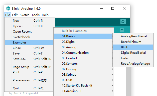
Open the Blink example
Open the LED blink example sketch: File > Examples >01.Basics > Blink.

Add Seeeduino to your Arduino IDE
Click on File > Preference, and fill Additional Boards Manager URLs with below url:https://raw.githubusercontent.com/Seeed-Studio/Seeeduino-Boards/master/package_seeeduino_index.json
Click OK to finish the setting. Then Click on Tools > Board > Boards Manager, find Seeeduino by Seeed Studio, and Install it.

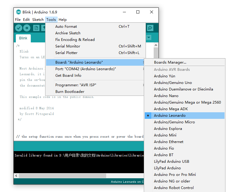
Select your board
You’ll need to select the entry in the Tools > Board menu that corresponds to your Arduino. Selecting a Seeeduino Mega 2560.

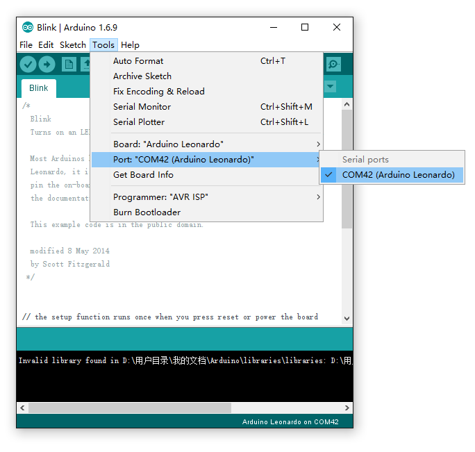
Select your serial port
Select the serial device of the Arduino board from the Tools | Serial Port menu. This is likely to be COM3 or higher (COM1 and COM2 are usually reserved for hardware serial ports). To find out, you can disconnect your Arduino board and re-open the menu; the entry that disappears should be the Arduino board. Reconnect the board and select that serial port.

Note
On the Mac, this should be something with /dev/tty.USBmodem.
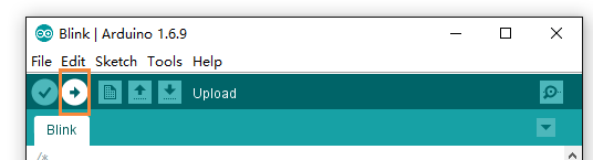
Upload the program
Now, simply click the “Upload” button in the environment. Wait a few seconds and if the upload is successful, the message “Done uploading.” will appear in the status bar.

A few seconds after the upload finishes, you should see the pin 13 (L) LED on the board start to blink (in orange). If it does, congratulations! You’ve gotten Arduino up-and-running. If you have problems, please see the troubleshooting suggestions.
Getting Started on Linux
For using on Linux, please go to Installing Arduino on Linux
Resources
- Schematic
- Pin Mapping
- References
FAQ
What is the different between Arduino Mega with Seeeduino Mega?
Seeeduino Mega is a powerful microcontroller derived from Arduino Mega. And there are the mainly difference list:
- Use a mini USB to power and program
- Add 3.3/5V system power switch
- Add automatic reset mode swtich
- Smaller size
Help us make it better
Thank you for choosing Seeed. A couple of months ago we initiated a project to improve our documentation system. What you are looking at now is the first edition of the new documentation system. Comparing to the old one, here is the progresses that we made:
- Replaced the old documentation system with a new one that was developed from Mkdocs, a more widely used and cooler tool to develop documentation system.
- Integrated the documentation system with our official website, now you can go to Bazaar and other section like Forum and Community more conveniently.
- Reviewed and rewrote documents for hundreds of products for the system’s first edition, and will continue migrate documents from old wiki to the new one.
An easy-to-use instruction is as important as the product itself. We are expecting this new system will improve your experience when using Seeed’s products. However since this is the first edition, there are still many things need to improve, if you have any suggestions or findings, you are most welcome to submit the amended version as our contributor or give us suggestions in the survey below, Please don’t forget to leave your email address so that we can reply.
Happy hacking