Raspberry Pi Motor Driver Board v1.0
Introduction
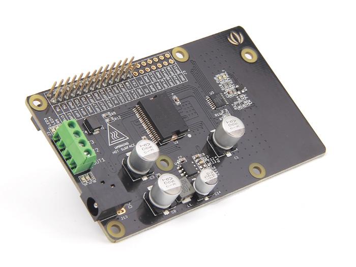
Raspberry Pi Motor Driver Board v1.0 is based on the Freescale MC33932 dual H-Bridge Power IC, which can control inductive loads with currents up to 5.0A peak per single bridge. It lets you drive two DC motors with your Raspberry Pi B/B+/A+ and Pi 2 Model B, controlling the speed and direction of each one independently.
Raspberry Pi Motor Driver Board v1.0 support a very wide range of input voltage from 6V~28V. otherwise ,the on board DC/DC converter support a very wide range of input voltage, and can provide a 5V power supply for the Raspberry Pi with 1000mA maximum current. So, you just need one power supply to drive the motors and power up the Raspberry Pi.

Features
- Output short-circuit protection (short to VPWR or GND)
- Over-current limiting (regulation) via internal constant-off-time PWM
- Temperature dependant current limit threshold reduction
- Raspberry Pi compatible
Specifications
| Item | Min | Typical | Max | Unit |
|---|---|---|---|---|
| Operating Voltage | 6 | / | 28 | VDC |
| DC/DC output: | / | 5V/1000mA | / | |
| Output Current (For Each Channel) | / | 2 (continuous operation) | 5 (peak) | A |
| PWM Frequency | / | / | 11 | kHz |
| Output Duty Range | 0 | / | 100 | % |
| Logic Input Voltage | -0.3 | / | 7 | V |
| Operating Temperature | -40 | / | 120 | ℃ |
| Dimensions | 91.20 * 56.15 * 32 | mm | ||
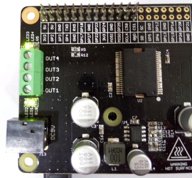
Hardware Overview

- J1:DC Input connector.
- J2:Motor Driver output connector.
- EN,FT:Jumpers for EN control and Fault flag detection.If short circuit the EN jumper, the EN signal was mapped to the D4 pin ,you can control the H-Bridge disable output or reset the Fault flag by D4 pin. If short circuit the FT jumper, the fault flag signal was mapped to D3 pin ,you can read the fault flag from the D3 pin ether.
- IO:Logic Voltage level Select Jumper. You can choose the control logic voltage level from this jumper.
- Power Supply: You have to power up the shield from the J1(DC input connector).The input voltage range can be set up to 6Vdc ~ 28Vdc.The on board DC/DC converter can convert the DC input voltage to 5Vdc output voltage to supply the logic circuit.The DC/DC converter can also power up the microcontroller board(Arduino/Seeeduino) form “5V” pin for maximun 100mA current.
- Motor Interface:Out 1 and Out 2 (Out 3 and Out 4) connect Motor A(B) for DC Motor.
Caution
Do not touch the H-bridge IC or PCB board during working. Its temperature can reach up to 100 degrees in the case of full load operating.Usage
This demo is using Raspberry Pi B to show that Raspberry Pi Motor Driver Board v1.0 be use to control DC motor forward and backward.
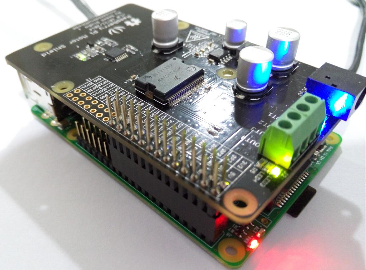
Hardware Installation
- Raspberry Pi B & Raspberry Pi Motor Driver Board v1.0
- Hardware connection as shown
Connect to network and power.
Software Part
1.Copy the code below;
#!/usr/bin/python
import RPi.GPIO as GPIO
import time
import signal
from PiSoftPwm import *
#print 'Go_1...'
#frequency = 1.0 / self.sc_1.GetValue()
#speed = self.sc_2.GetValue()
class Motor():
def __init__(self):
# MC33932 pins
self.PWMA = 25
self.PWMB = 22
self._IN1 = 23
self._IN2 = 24
self._IN3 = 17
self._IN4 = 27
# Initialize PWMA PWMB
GPIO.setmode(GPIO.BCM)
GPIO.setup(self.PWMA, GPIO.OUT)
GPIO.setup(self.PWMB, GPIO.OUT)
GPIO.output(self.PWMA, True)
GPIO.output(self.PWMB, True)
# Initialize PWM outputs
self.OUT_1 = PiSoftPwm(0.1, 100, self._IN1, GPIO.BCM)
self.OUT_2 = PiSoftPwm(0.1, 100, self._IN2, GPIO.BCM)
self.OUT_3 = PiSoftPwm(0.1, 100, self._IN3, GPIO.BCM)
self.OUT_4 = PiSoftPwm(0.1, 100, self._IN4, GPIO.BCM)
# Close pwm output
self.OUT_1.start(0)
self.OUT_2.start(0)
self.OUT_3.start(0)
self.OUT_4.start(0)
self.frequency = 0.01
self.duty = 60
def Setting(self, frequency, duty):
self.frequency = frequency
self.duty = duty
def Go_1(self):
self.OUT_1.changeBaseTime(self.frequency)
self.OUT_2.changeBaseTime(self.frequency)
self.OUT_1.changeNbSlicesOn(self.duty)
self.OUT_2.changeNbSlicesOn(0)
def Back_1(self):
self.OUT_1.changeBaseTime(self.frequency)
self.OUT_2.changeBaseTime(self.frequency)
self.OUT_1.changeNbSlicesOn(0)
self.OUT_2.changeNbSlicesOn(self.duty)
def Go_2(self):
self.OUT_3.changeBaseTime(self.frequency)
self.OUT_4.changeBaseTime(self.frequency)
self.OUT_3.changeNbSlicesOn(0)
self.OUT_4.changeNbSlicesOn(self.duty)
def Back_2(self):
self.OUT_3.changeBaseTime(self.frequency)
self.OUT_4.changeBaseTime(self.frequency)
self.OUT_3.changeNbSlicesOn(self.duty)
self.OUT_4.changeNbSlicesOn(0)
def Stop():
self.OUT_1.changeNbSlicesOn(0)
self.OUT_2.changeNbSlicesOn(0)
self.OUT_3.changeNbSlicesOn(0)
self.OUT_4.changeNbSlicesOn(0)
if __name__=="__main__":
motor=Motor()
# Called on process interruption. Set all pins to "Input" default mode.
def endProcess(signalnum = None, handler = None):
motor.OUT_1.stop()
motor.OUT_2.stop()
motor.OUT_3.stop()
motor.OUT_4.stop()
motor.GPIO.cleanup()
exit(0)
# Prepare handlers for process exit
signal.signal(signal.SIGTERM, endProcess)
signal.signal(signal.SIGINT, endProcess)
signal.signal(signal.SIGHUP, endProcess)
signal.signal (signal.SIGQUIT, endProcess)
motor.Setting(0.01, 60)
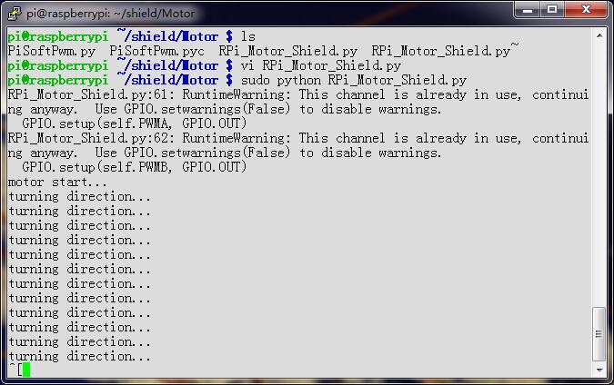
print 'motor start...'
while True:
print 'turning direction...'
motor.Go_1()
time.sleep(1)
motor.Back_1()
time.sleep(1)
motor.Go_2()
time.sleep(1)
motor.Back_2()
time.sleep(1)
2.Saved in the Raspberry Pi, according to your own path.
3.Run this program. LED1, LED2 on Raspberry Pi Motor Driver Board v1.0 will alternately light up; LED3, LED4 will also alternately light up.
It means Out 1 and Out 2 (Out 3 and Out 4) connect Motor A(B) forward and back.
4.You can see phenomemon as follows:
Serial console:
Raspberry Pi Motor Driver Board v1.0: Green LED and Blue LED alternately light up.
Resources
- Eagle file Raspberry Pi Motor Driver Board v1.0
- PDF Raspberry Pi Motor Driver Board v1.0
- MC33932VW Datasheet
- TD1519A Datasheet
Help us make it better
Thank you for choosing Seeed. A couple of months ago we initiated a project to improve our documentation system. What you are looking at now is the first edition of the new documentation system. Comparing to the old one, here is the progresses that we made:
- Replaced the old documentation system with a new one that was developed from Mkdocs, a more widely used and cooler tool to develop documentation system.
- Integrated the documentation system with our official website, now you can go to Bazaar and other section like Forum and Community more conveniently.
- Reviewed and rewrote documents for hundreds of products for the system’s first edition, and will continue migrate documents from old wiki to the new one.
An easy-to-use instruction is as important as the product itself. We are expecting this new system will improve your experience when using Seeed’s products. However since this is the first edition, there are still many things need to improve, if you have any suggestions or findings, you are most welcome to submit the amended version as our contributor or give us suggestions in the survey below, Please don’t forget to leave your email address so that we can reply.
Happy hacking
댓글 없음:
댓글 쓰기