Raspberry Pi Relay Board v1.0
Introduction
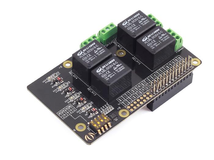
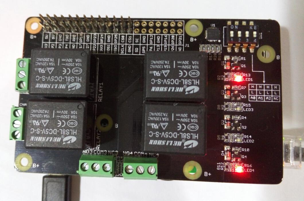
The Relay Shield utilizes four high quality relays and provides NO/NC interfaces that control the load of high current. Which means it could be a nice solution for controlling devices that couldn’t be directly controlled by IIC bus. Standardized shield form factor enables smoothly connection with the Raspberry Pi . The shield also has four dynamic indicators show the on/off state of each relay.

Features
- Raspberry Pi compatible
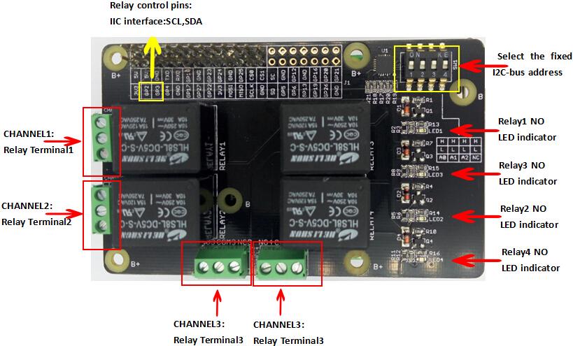
- Interface: IIC, Three hardware SW1 (1, 2, 3) select the fixed I2C-bus address
- Relay screw terminals
- Standardized shield shape and design
- LED working status indicators for each relay
- COM, NO (Normally Open), and NC (Normally Closed) relay pins for each relay
- High quality relays
- Working status indicators for each relay
Specifications
| Item | Min | Typical | Max | Unit |
|---|---|---|---|---|
| Supply Voltage | 4.75 | 5 | 5.5 | VDC |
| Working Current | 10 | / | 360 | mA |
| Switching Voltage | / | / | 30/250 | VDC/VAC |
| Switching Current | / | / | 15 | A |
| Frequency | / | 1 | / | HZ |
| Switching Power | / | / | 2770VA/240 | W |
| Relay Life | 100,000 | / | / | Cycle |
| Dimensions | 91.20 * 56.15 * 32 | mm | ||
Caution
Place 2 layers of electrical tape on the top of the Arduino's usb connector. This will prevent the relay shield from making contact. Do not operate voltage more than 35V DC.Hardware Overview
Usage
Here we can use serial console to change the state of each the relay or all relays.
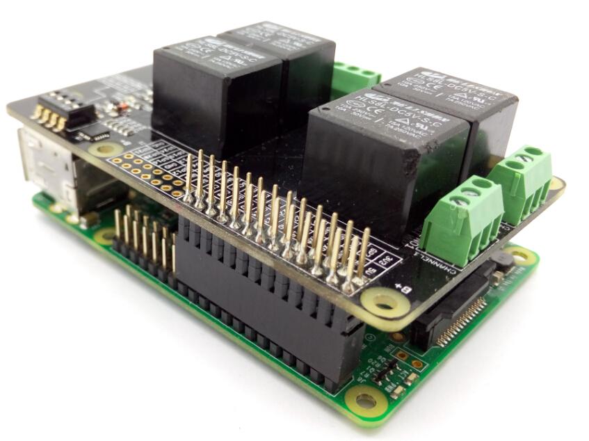
Hardware Installation
- Raspberry Pi B & Raspberry Pi Motor Driver Board v1.0
- Hardware connection as shown
We can select the fixed I2C-bus address by SW1.
Software Part
1.Copy the code below;
    import time
    import smbus
    import signal
    import sys

    bus = smbus.SMBus(1)    # 0 = /dev/i2c-0 (port I2C0), 1 = /dev/i2c-1 (port I2C1)


    class Relay():
        global bus
        def __init__(self):
        self.DEVICE_ADDRESS = 0x20      #7 bit address (will be left shifted to add the read write bit)
        self.DEVICE_REG_MODE1 = 0x06
        self.DEVICE_REG_DATA = 0xff
        bus.write_byte_data(self.DEVICE_ADDRESS, self.DEVICE_REG_MODE1, self.DEVICE_REG_DATA)

        def ON_1(self):
            print 'ON_1...'
            self.DEVICE_REG_DATA &= ~(0x1<<0)
            bus.write_byte_data(self.DEVICE_ADDRESS, self.DEVICE_REG_MODE1, self.DEVICE_REG_DATA)
        def ON_2(self):
            print 'ON_2...'
            self.DEVICE_REG_DATA &= ~(0x1<<1)
            bus.write_byte_data(self.DEVICE_ADDRESS, self.DEVICE_REG_MODE1, self.DEVICE_REG_DATA)
        def ON_3(self):
            print 'ON_3...'
            self.DEVICE_REG_DATA &= ~(0x1<<2)
            bus.write_byte_data(self.DEVICE_ADDRESS, self.DEVICE_REG_MODE1, self.DEVICE_REG_DATA)
        def ON_4(self):
            print 'ON_4...'
            self.DEVICE_REG_DATA &= ~(0x1<<3)
            bus.write_byte_data(self.DEVICE_ADDRESS, self.DEVICE_REG_MODE1, self.DEVICE_REG_DATA)

        def OFF_1(self):
            print 'OFF_1...'
            self.DEVICE_REG_DATA |= (0x1<<0)
            bus.write_byte_data(self.DEVICE_ADDRESS, self.DEVICE_REG_MODE1, self.DEVICE_REG_DATA)

        def OFF_2(self):
            print 'OFF_2...'
            self.DEVICE_REG_DATA |= (0x1<<1)
            bus.write_byte_data(self.DEVICE_ADDRESS, self.DEVICE_REG_MODE1, self.DEVICE_REG_DATA)

        def OFF_3(self):
            print 'OFF_3...'
            self.DEVICE_REG_DATA |= (0x1<<2)
            bus.write_byte_data(self.DEVICE_ADDRESS, self.DEVICE_REG_MODE1, self.DEVICE_REG_DATA)

        def OFF_4(self):
            print 'OFF_4...'
            self.DEVICE_REG_DATA |= (0x1<<3)
            bus.write_byte_data(self.DEVICE_ADDRESS, self.DEVICE_REG_MODE1, self.DEVICE_REG_DATA)

        def ALLON(self):
            print 'ALLON...'
            self.DEVICE_REG_DATA &= ~(0xf<<0)
            bus.write_byte_data(self.DEVICE_ADDRESS, self.DEVICE_REG_MODE1, self.DEVICE_REG_DATA)

        def ALLOFF(self):
            print 'ALLOFF...'
            self.DEVICE_REG_DATA |= (0xf<<0)
            bus.write_byte_data(self.DEVICE_ADDRESS, self.DEVICE_REG_MODE1, self.DEVICE_REG_DATA)


    if __name__=="__main__":
        relay = Relay()
        # Called on process interruption. Set all pins to "Input" default mode.
        def endProcess(signalnum = None, handler = None):
            relay.ALLOFF()
            sys.exit()

        signal.signal(signal.SIGINT, endProcess)

        while True:
            ct = raw_input("input: ")
            if ct == '1on':
                relay.ON_1()
            elif ct == '2on':
                relay.ON_2()
            elif ct == '3on':
                relay.ON_3()
            elif ct == '4on':
                relay.ON_4()
            elif ct == '1off':
                relay.OFF_1()
            elif ct == '2off':
                relay.OFF_2()
            elif ct == '3off':
                relay.OFF_3()
            elif ct == '4off':
                relay.OFF_4()
            elif ct == 'allon':
                relay.ALLON()
            elif ct == 'alloff':
                relay.ALLOFF()
2.Saved in the Raspberry Pi, according to your own path.
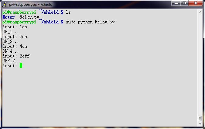
3.Run this program.
The terminal will print “input:”,then you can change the state of each the relay or all relays. You should type input like “1on”,“2on”,“3on” or “1off”,“allon”,“alloff”
4.Note that you should select set the correct I2C-bus address.
You can see :
Terminal:
Raspberry Pi Relay Board v1.0: Whichever relay is turned on, the corresponding LED will turn on.
Resources
- Raspberry_Pi_Relay_Board_v1.0_sch_pcb
- Raspberry_Pi_Relay_Board_v1.0_PDF
- HLS8L Datasheet
- PCAL9535A Datasheet
Help us make it better
Thank you for choosing Seeed. A couple of months ago we initiated a project to improve our documentation system. What you are looking at now is the first edition of the new documentation system. Comparing to the old one, here is the progresses that we made:
- Replaced the old documentation system with a new one that was developed from Mkdocs, a more widely used and cooler tool to develop documentation system.
- Integrated the documentation system with our official website, now you can go to Bazaar and other section like Forum and Community more conveniently.
- Reviewed and rewrote documents for hundreds of products for the system’s first edition, and will continue migrate documents from old wiki to the new one.
An easy-to-use instruction is as important as the product itself. We are expecting this new system will improve your experience when using Seeed’s products. However since this is the first edition, there are still many things need to improve, if you have any suggestions or findings, you are most welcome to submit the amended version as our contributor or give us suggestions in the survey below, Please don’t forget to leave your email address so that we can reply.
Happy hacking
댓글 없음:
댓글 쓰기