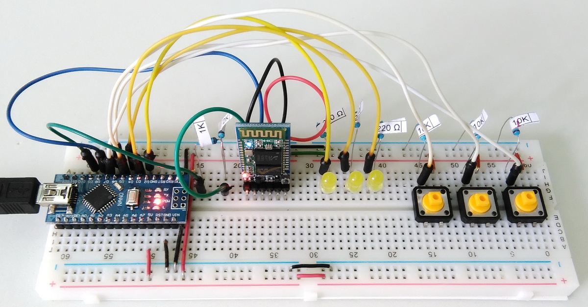
Now that we have two way communication working let’s add a couple more LEDs and two more switches.
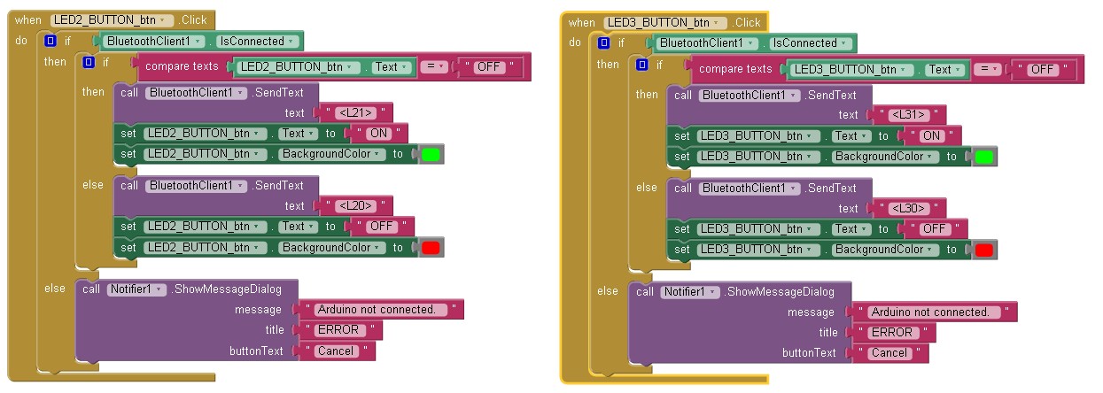
In App Inventor I had added two more buttons to control the extra LEDs
Android App
In the designer I have added two horizontal arrangements. These are as containers for the LED labels and a LED buttons. The App Inventor 2 aia file can be downloaded at the bottom of the page.
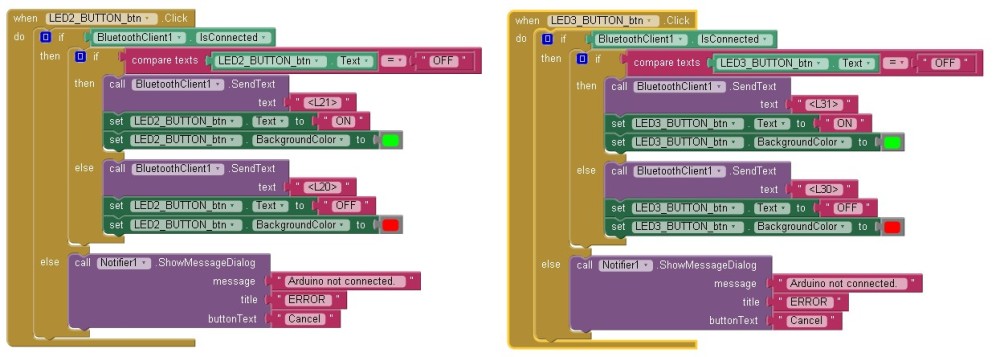
To handle the 2 new buttons there are 2 extra button click event functions. One function for button #2 and one for button #3. The new button click functions are copies of the button #1 click function except the references to the button have been changed so that the correct button is updated and the correct command is sent to the Arduino.
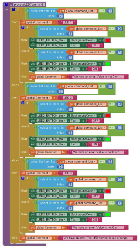
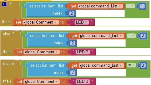
We have extra commands for the two new switches that we need to take care of: <L20> <L21> <L30> <L31> These are handled by an extended processLEDCommand function: Because we have more than 1 LED we need to check to see which LED the command is for. This is done through the main if/then control. This tests for LED1, LED2 and LED3 in turn.
Arduino
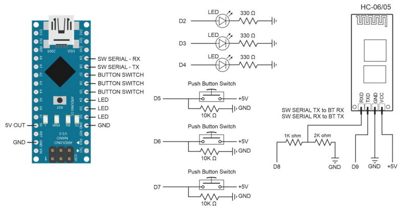
On the Arduino side I added 2 more LEDs and 2 more switches. And of course the sketch needs to be updated to accommodate the extra components.
When dealing with 2 or 3 of the same component keeping the sketch simple is probably the best way to go, therefore, I simply duplicate the code used for the 1 LED and changed the references.
For 2 or 3 LEDs or switches I don’t see the need to complicate the code. The extra for loops required don’t really save space and make the code harder to debug. Duplicating code blocks may seem wasteful but it keeps the code as simple as possible which makes it easier to understand.
There are now extra commands and these are handled by adding extra conditions to the processCommand() function. Again, I have kept it simple and just duplicated the existing code and changed the values to accommodate LED2 and LED3. L10 becomes L20 and L30, etc.
Since we are using fixed length commands we know that the first character is the command type, in this case L for LED, the second character is the LED number and the third values is either a 0 or a 1 (off or on). This means we could use a slightly different if/then structure:
if(receivedChars[0]=='L')// Do we have an LED command?{if(receivedChars[1]=='1')// Is the command for LED number 1?{if(receivedChars[2]=='0')// Is the LED off?{
digitalWrite(LED1_PIN,LOW);
LED1_State = LOW;
Serial.println("LED1 LOW");}elseif(receivedChars[2]=='1')// Or is the LED on?{
digitalWrite(LED1_PIN,LOW);
LED1_State = LOW;
Serial.println("LED1 LOW");}}// We already know we have an LED command so no need to recheck.if(receivedChars[1]=='2')// Is the command for LED number 2?{if(receivedChars[2]=='0')// Is the LED off?{
digitalWrite(LED2_PIN,LOW);
LED2_State = LOW;
Serial.println("LED2 LOW");}elseif(receivedChars[2]=='1')// Or is the LED on?{
digitalWrite(LED2_PIN,LOW);
LED1_State = LOW;
Serial.println("LED2 LOW");}}// code for LED #3 not shown.}
However, this is still slightly cumbersome and not as easy to read. When using
if(strcmp("L10",receivedChars)==0)
you can see straight away what is happening. The code is looking for “L10″; is it LED #1 and is it off.
Likewise for the checkSwitch() function. I duplicated the code for the extra switchs. This means there are 3 code blocks that are almost identical but it keeps it easy to read.
Although I have just advocated keeping the code as simple as possible you can see that the above has 3 code blocks that are almost exactly the same. This could be made better by using single code block with a variable for the switch pin and by using arrays for the switch variables and passing the pin for the switch to check to the function.
Let’s see what it would look like.
First off we put the pin values and status variables in to arrays:
// Constants for hardwareconst byte LED_PIN[]={2,3,4};const byte SWITCH_PIN[]={5,6,7};// general variables
boolean LED_State[]={false,false,false};
boolean switch_State[]={false,false,false};
boolean oldswitch_State[]={false,false,false};
Since we now have arrays we can use them when initialising the pins:
void setup(){for(byte pin =0; pin <3; pin++){// Set the button switch pins for input
pinMode(SWITCH_PIN[pin], INPUT);// Set the LED pins for output and make them LOW
pinMode(LED_PIN[pin], OUTPUT); digitalWrite(LED_PIN[pin],LOW);}
In the main loop we now use a loop when checking the switches and we pass the switch number to the checkSwitch() function. Rather than checking all 3 switches in one go we now check one at a time by telling the function which one to check. You could move the for loop to inside the checkSwitch() function and call it just once if you liked.
void loop(){for(byte switchNum =1; switchNum <4; switchNum++){
checkSwitch(switchNum);}
recvWithStartEndMarkers();// check to see if we have received any new commandsif(newData){ processCommand();}// if we have a new command do something about it}
In the checkSwitch() function we now create the commands on the fly rather than having 3 sets of commands hard coded in to the sketch. The command is created by using a dummy command and then replacing the LED number and the LED status.
We now have the following and although it is much shorter it is also harder to understand.
void checkSwitch( byte pos){// pos = 1,2,3. Array pos = 0,1,2 so convert by subtracting 1
pos = pos-1;// very simple debouce.
boolean state1 = digitalRead(SWITCH_PIN[pos]); delay(1);
boolean state2 = digitalRead(SWITCH_PIN[pos]); delay(1);
boolean state3 = digitalRead(SWITCH_PIN[pos]); delay(1);if((state1 == state2)&&(state1==state3)){
switch_State[pos]= state1;if((switch_State[pos]== HIGH)&&(oldswitch_State[pos]== LOW)){
LED_State[pos]=! LED_State[pos];// flip the status.char TMPcmd[8]="<L,1,0>";
TMPcmd[3]= pos+1+48;// pos+1 is the LED number; 1,2, or 3. // Convert a numeric value to ascii by adding 48
TMPcmd[5]= LED_State[pos]+48;// LED_State should be 0 or 1
BTserial.print(TMPcmd);
digitalWrite(LED_PIN[pos],LED_State[pos]);
Serial.println(TMPcmd);}
oldswitch_State[pos]= switch_State[pos];}}
And in the processCommand() function we have done away with the long list of if/thens and reduced it to just a few lines.
void processCommand(){
Serial.print("receivedChars = "); Serial.println(receivedChars);if(receivedChars[0]=='L')// do we have a LED command?{// we know the LED command has a fixed length "L10"// and the value at pos 1 is the LED and the value at pos 2 is 0 or 1 (on/off). // 0 and 1 is the same as LOW and HIGH.
byte LEDnum = receivedChars[1]-48;// convert ascii to value by subtracting 48
boolean LEDstatus = receivedChars[2]-48;
digitalWrite(LED_PIN[LEDnum-1],LEDstatus);
LED_State[LEDnum-1]= LEDstatus;}
receivedChars[0]='\0';
newData =false;}
This could be reduced further by removing the LEDnum and LEDstatus variables but you would end up with
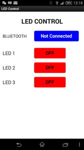 In App Inventor I had added two more buttons to control the extra LEDs
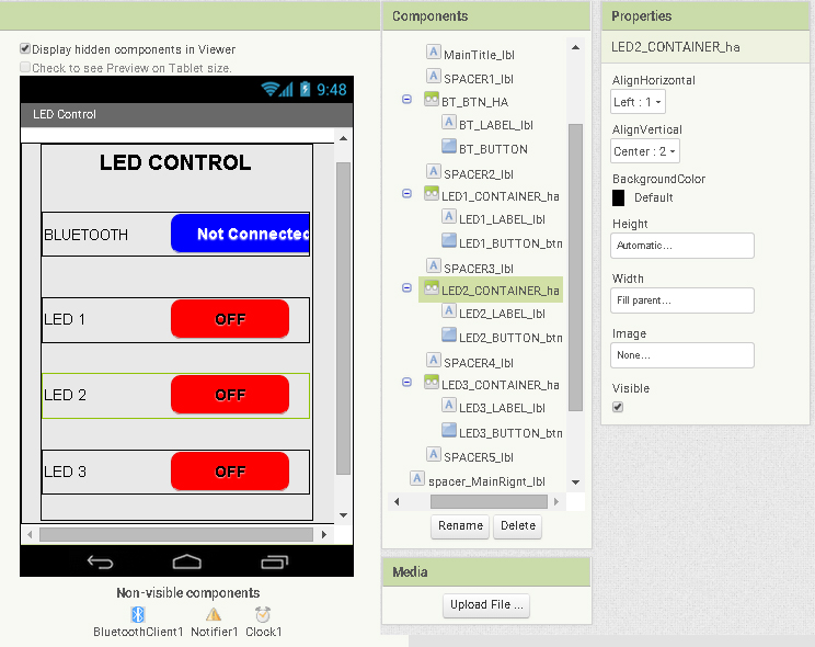


댓글 없음:
댓글 쓰기