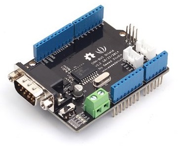
CAN-BUS Shield V1.2
Introduction
CAN-BUS is a common industrial bus because of its long travel distance, medium communication speed and high reliability. It is commonly found on modern machine tools and as an automotive diagnostic bus.
This CAN-BUS Shield adopts MCP2515 CAN Bus controller with SPI interface and MCP2551 CAN transceiver to give your Arduino/Seeeduino CAN-BUS capability. With an OBD-II converter cable added on and the OBD-II library imported, you are ready to build an onboard diagnostic device or data logger.
Version
This document applies to the following version of products:
| Version | Released Date | How to Buy |
|---|---|---|
| CAN BUS Shield V1.0 | Oct 14, 2012 |  |
| CAN BUS Shield V1.1 | Aug 10, 2013 | |
| CAN BUS Shield V1.2 | Jan 5, 2015 |  |
What’s new in CAN BUS Shield V1.2 Pads on the back of PCBA Change terminal resistor to 120 Ohm
Features
- Implements CAN V2.0B at up to 1 Mb/s
- SPI Interface up to 10 MHz
- Standard (11 bit) and extended (29 bit) data and remote frames
- Two receive buffers with prioritized message storage
- Industrial standard DB-9 connector
- LED indicators
Note
CAN BUS Shield Work well with Arduino UNO (ATmega328), Arduino Mega (ATmega1280/2560) as well as Arduino Leonardo (ATmega32U4).
Hardware Overview
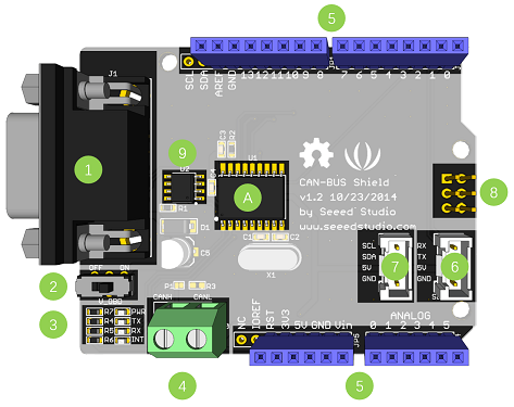
- DB9 Interface - to connect to OBDII Interface via a DBG-OBD Cable.
- V_OBD - If get power from OBDII Interface (from DB9)
- Led Indicator:
- PWR: power
- TX: blink when the data is sending
- RX: blink when there’s data coming
- INT: data interrupt
- Terminal - CAN_H and CAN_L
- Arduino UNO pin out
- Serial Grove connector
- I2C Grove connector
- ICSP pins
- IC - MCP2551, a high-speed can transceiver (datasheet)
- IC - MCP2515, stand-alone CAN controller with SPI interface (datasheet)
Warning
When you use more than two CAN Bus Shield in one net, you should think about the impedance. You can just cut P1 in the PCB with a knife, or just remove R3 on the PCB.
Pin map
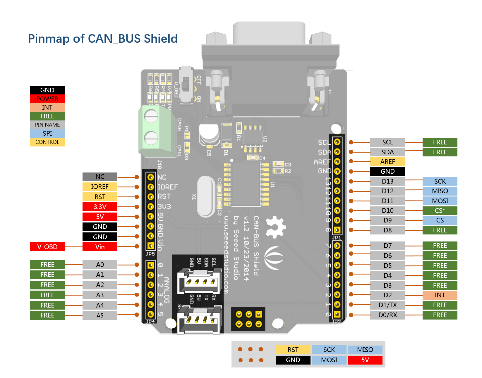
Note
The pin FREE is available for the other usages.
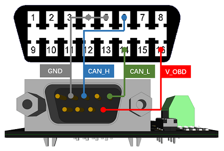
DB9&OBDii Interface
CS pin
SPI_CS pin of V1.2 is default to D9. If you want to change it to D10.
- Step1: Take a look at the back of the PCBA, you will find a pad named CS.
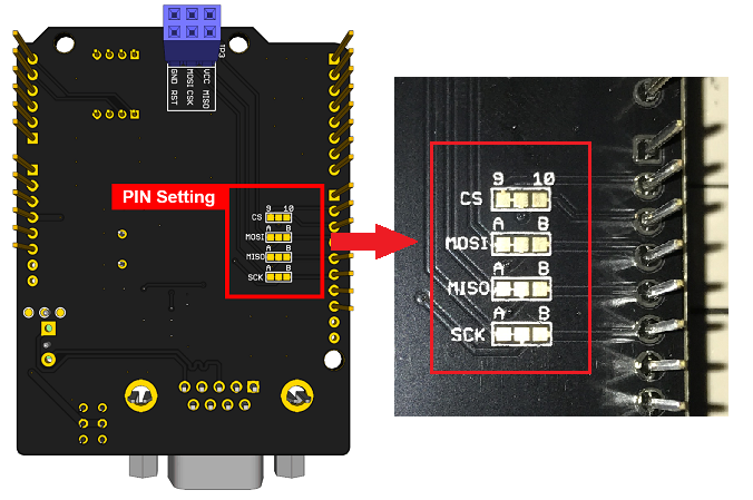
- Step2: Cut the wire that connect pad9 and the middle pad

- Step3:Solder the middle pad and pad 10.

Warning
Be careful with the box cutter, it’s easy to hurt yourself or the PCBA.
SPI pins
The SPI pins (SCK, MISO, MOSI) is default to the ICSP pins. But for some Boards, maybe the SPI pins is at D11~D13, if so you need to change something in the PCBA. Take a look that the back of the PCBA, there’re three pads, MOSI, MISO and SCK, they are default to A. You can change them to B if needed.
Note
For Arduino UNO, Arduino Mega, Arduino Leonardo and any others AVR based Arduino boards, default is working.
Warning
Be careful when you are going to change SPI pins, it’s easy to hear yourself or the PCBA.
Getting Started
Here’s a simple demo to show you how CAN-BUS Shield works. In this demo we need 2 piece of CAN-BUS Shield as well as Arduino/Seeeduino.
Note
This demo is built under Arduino IDE version 1.6.9.
STEP1: What do we need
| Name | Function | Qty | Link |
|---|---|---|---|
| CAN-BUS Shield | CAN Bus communication | 2 | link |
| Seeeduino V4.2 | Controller | 2 | link |
| Jumper Wire | connection | 2 | link |
STEP2: Hardware Connection
Insert each CAN-BUS Shield to Seeeduino V4.2, and connect the 2 CAN-BUS Shield together via 2 jumper wires. Shown as below images.
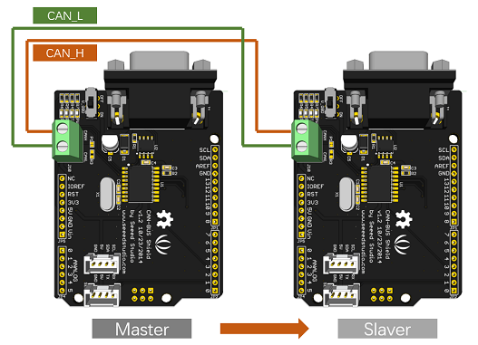
Note
CAN_H to CAN_H, CAN_L to CAN_L
STEP3: Software
Click on the below button to download the library.

Install the library to your Arduino IDE when it is downloaded.
Of of the node (a node means Seeeduino + CAN_BUS Shield) act as master, the other act as slaver. The master will send data to slaver constantly.
Note
Each node can act at master before the code is uploaded.
Open the send example (File > Examples > CAN_BUS_Shield-master > send) and upload to the master.
Open the receive_check example (File > Examples > CAN_BUS_Shield-master > receive_check) and upload to the slaver.
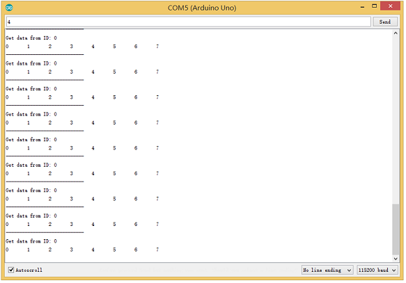
STEP4: View Result
Open the Serial Monitor of Arduino IDE(slaver), you will get the data sent from the master.
APIs
1. Set the Baud rate
This function is used to initialize the baud rate of the CAN Bus system.
The available baud rates are listed as follows:
#define CAN_5KBPS    1
#define CAN_10KBPS   2
#define CAN_20KBPS   3
#define CAN_25KBPS   4
#define CAN_31K25BPS 5
#define CAN_33KBPS   6
#define CAN_40KBPS   7
#define CAN_50KBPS   8
#define CAN_80KBPS   9
#define CAN_83K3BPS  10
#define CAN_95KBPS   11
#define CAN_100KBPS  12
#define CAN_125KBPS  13
#define CAN_200KBPS  14
#define CAN_250KBPS  15
#define CAN_500KBPS  16
#define CAN_666kbps  17
#define CAN_1000KBPS 18
2. Set Receive Mask and Filter
There are 2 receive mask registers and 5 filter registers on the controller chip that guarantee you get data from the target device. They are useful especially in a large network consisting of numerous nodes.
We provide two functions for you to utilize these mask and filter registers. They are:
Mask:
init_Mask(unsigned char num, unsigned char ext, unsigned char ulData);
Filter:
init_Filt(unsigned char num, unsigned char ext, unsigned char ulData);
- num represents which register to use. You can fill 0 or 1 for mask and 0 to 5 for filter.
- ext represents the status of the frame. 0 means it’s a mask or filter for a standard frame. 1 means it’s for a extended frame.
- ulData represents the content of the mask of filter.
3. Check Receive
The MCP2515 can operate in either a polled mode, where the software checks for a received frame, or using additional pins to signal that a frame has been received or transmit completed.
Use the following function to poll for received frames.
INT8U MCP_CAN::checkReceive(void);
The function will return 1 if a frame arrives, and 0 if nothing arrives.
4. Get CAN ID
When some data arrive, you can use the following function to get the CAN ID of the “send” node.
INT32U MCP_CAN::getCanId(void)
5. Send Data
CAN.sendMsgBuf(INT8U id, INT8U ext, INT8U len, data_buf);
It is a function to send data onto the bus. In which:
- id represents where the data come from.
- ext represents the status of the frame. ‘0’ means standard frame. ‘1’ means extended frame.
- len represents the length of this frame.
- data_buf is the content of this message.
For example, In the ‘send’ example, we have:
unsigned char stmp[8] = {0, 1, 2, 3, 4, 5, 6, 7};
CAN.sendMsgBuf(0x00, 0, 8, stmp); //send out the message 'stmp' to the bus and tell other devices this is a standard frame from 0x00.
6. Receive Data
The following function is used to receive data on the ‘receive’ node:
CAN.readMsgBuf(unsigned char len, unsigned char buf);
In conditions that masks and filters have been set. This function can only get frames that meet the requirements of masks and filters.
- len represents the data length.
- buf is where you store the data.
Generate a New BaudRate
We had provided many frequently-used baud rate, as below:
#define CAN_5KBPS    1
#define CAN_10KBPS   2
#define CAN_20KBPS   3
#define CAN_25KBPS   4
#define CAN_31K25BPS 5
#define CAN_33KBPS   6
#define CAN_40KBPS   7
#define CAN_50KBPS   8
#define CAN_80KBPS   9
#define CAN_83K3BPS  10
#define CAN_95KBPS   11
#define CAN_100KBPS  12
#define CAN_125KBPS  13
#define CAN_200KBPS  14
#define CAN_250KBPS  15
#define CAN_500KBPS  16
#define CAN_666kbps  17
#define CAN_1000KBPS 18
Yet you may still can’t find the rate you want. Here we provide a software to help you to calculate the baud rate you need.
Click here to download the software, it’s in Chinese, but never mind, it’s easy to use.

Note
This software support Windows system only. If you can’t open it, please free to contact loovee@seeed.cc for help.
Open the software, what you need to do is set the baud rate you want, and do some simple setting, then click calculate.
Then you will get some data, cfg1, cfg2 and cfg3.
You need to add some code to the library.
Open mcp_can_dfs.h, you need to add some code at about line 272:
#define MCP_16MHz_xxxkBPS_CFG1 (cfg1)    // xxx is the baud rate you need
#define MCP_16MHz_xxxkBPS_CFG2 (cfg2)
#define MCP_16MHz_xxxkBPS_CFG3 (cfg2)
Then let’s go to about line 390, add some code:
#define CAN_xxxKBPS NUM // xxx is the baudrate you need, and NUM is a number, you need to get a different from the other rates.
Open mcp_can.cpp, goto the function mcp2515_configRate(at about line 190), then add some code:
case (CAN_xxxKBPS):
    cfg1 = MCP_16MHz_xxxkBPS_CFG1;
    cfg2 = MCP_16MHz_xxxkBPS_CFG2;
    cfg3 = MCP_16MHz_xxxkBPS_CFG3;
    break;
Then you can use the baud rate you need. And please give me a pull request at github when you use a new rate, so I can add it to the library to help the other guys.
Projects
If you want to make some awesome projects with CAN-BUS shield, here’s some projects for reference.
Volkswagen CAN BUS Gaming
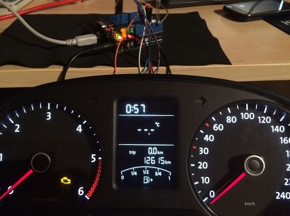
Ever wanted to play a car/truck simulator with a real dashboard on your PC? Me too! I’m trying to control a VW Polo 6R dashboard via CAN Bus with an Arduino Uno and a Seeed CAN Bus Shield. Inspired by Silas Parker. Thanks to Sepp and Is0-Mick for their great support!
Hack your vehicle CAN-BUS
Modern Vehicles all come equipped with a CAN-BUS Controller Area Network, Instead of having a million wires running back and forth from various devices in your car to the battery, its making use of a more clever system.
All electronic functions are connected to the TIPM, (Totally integrated Power Module), such as solenoids/relays to lock the doors or mini motors to wind the windows etc.
From each node (IE Switch pod that controls your windows or electric door locks) it broadcasts a message across the CAN. When the TIPM detects a valid message it will react accordingly like, lock the doors, switch on lights and so on.
Resources
- 【PDF】CAN-BUS Shield V1.2 Schmatics
- 【Eagle】Schematic of CAN-BUS Shield V1.2
- 【Library】Arduino Library for CAN-BUS Shield
- 【Datasheet】MCP2515 datasheet
- 【Datasheet】MCP2551 datasheet
- 【Demo】An OBD Demo
- 【Tool】MCP2515 Baud Rate Tool
FAQ
Q1: I can’t get data from other CAN device.
- Check if the connection is right
- Check if the baud rate set right
Q2: The serial monitor print Init Fail.
- Check if the CS pin set right in the code. For CAN Bus Shield V1.1/1.2, CS pin is default to D9, others default to D10.
Q3. Where can I find technical support if I have some other issue.
- You can post a question to Seeed Forum or send an email to techsupport@seeed.cc.
Help us make it better
Thank you for choosing Seeed. A couple of months ago we initiated a project to improve our documentation system. What you are looking at now is the first edition of the new documentation system. Comparing to the old one, here is the progresses that we made:
- Replaced the old documentation system with a new one that was developed from Mkdocs, a more widely used and cooler tool to develop documentation system.
- Integrated the documentation system with our official website, now you can go to Bazaar and other section like Forum and Community more conveniently.
- Reviewed and rewrote documents for hundreds of products for the system’s first edition, and will continue migrate documents from old wiki to the new one.
An easy-to-use instruction is as important as the product itself. We are expecting this new system will improve your experience when using Seeed’s products. However since this is the first edition, there are still many things need to improve, if you have any suggestions or findings, you are most welcome to submit the amended version as our contributor or give us suggestions in the survey below, Please don’t forget to leave your email address so that we can reply.
Happy hacking
댓글 없음:
댓글 쓰기