Seeeduino Cloud
Introduction
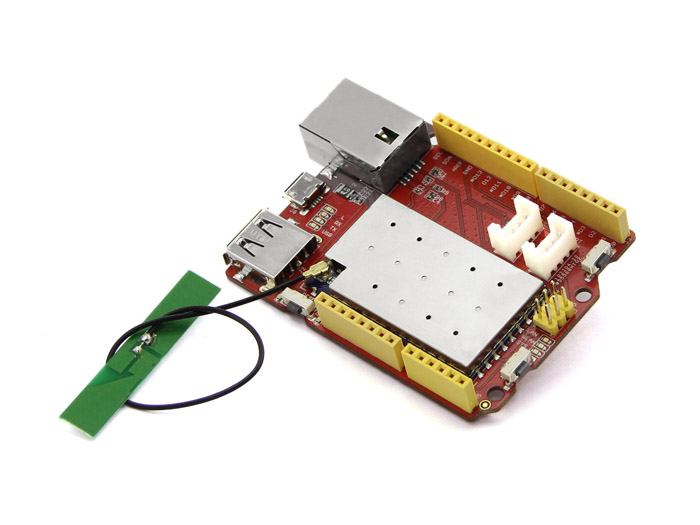
Seeeduino Cloud is a microcontroller board based on Dragino WiFi IoT module HE and ATmega32u4. HE is a high performance, low cost 150M, 2.4G WiFi module which means “core” in Chinese and with an Open Source OpenWrt system inside. Seeeduino Cloud is also an Arduino compatible board, 100% compatible to Grove, shield and IDEs(Arduino IDE 1.5.3 and later). Except for the normal interface of Arduino, Seeeduino Cloud has built-in Ethernet and WiFi support, a USB-A port which makes it very suitable for those prototype design that need network connection and mass storage. It is also a good idea to make Seeeduino Cloud to be an IoT gateway.

Application Ideas
- Internet of Things
- Smart House
- Learning
Here are some funny projects for your reference.
| Simple Wi-Fi Messager | Send data to Google Docs | Solar Panel Monitoring System |
|---|---|---|
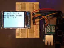 | 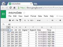 |  |
| Make it Now | Make it Now | Make it Now |
Features
- Compatible with Arduino Yun
- Based on Dragino WiFi IoT module HE
- Open Source OpenWrt system inside
- Support 2.4Ghz WiFi, 802.11 b/g/n
- Support Ethernet
- Support USB 2.0
- On-board Grove connectors
Specification
Because Seeeduino Cloud has two processors, this section shows the characteristics of each one in two separate tables.
Dragino HE Module
| Parameter | Value |
|---|---|
| CPU | ATHEROS AR9331 |
| Clock Speed | 400MHz |
| RAM | 64MB |
| Flash | 16MB |
| OS | OpenWrt |
| Interfaces | 2 x RJ45, 1 x USB Host, 1 x UART, 14 multiplex GPIOs |
| Power | 3.3V Power Input |
| WiFi | Support 150M 2.4Ghz WiFi, 802.11 b/g/n |
AVR Arduino Microcontroller
| Parameter | Value |
|---|---|
| Microcontroller | ATmega32u4 |
| Flash Memory | 32KB |
| SRAM | 2.5kB |
| EEPROM | 1kB |
| Clock Speed | 16MHz |
| Operating Voltage | 5V |
| Digital I/O Pins | 20 |
| PWM Channels | 7 |
| Analog Input Channels | 12 |
Hardware Overview
The images below show an overview of Seeeduino Cloud hardware features. The pin-out and alternate functions of various pins of Seeeduino Cloud are shown in the pin-out diagram. This could be used as a quick reference.
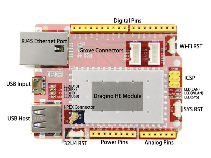
- RJ45 Ethernet Port The LAN Port is connected to ATHEROS AR9331 and has its own IP address that can be used for Internet connection and device management.
- USB Input USB Port is used to connect the board to your PC for programming and for powering up. Micro USB is the ubiquitous version of USB, found in most Android phones, and other devices. You probably have dozens of these cables laying around your house.
- USB HOST Seeeduino Cloud provides USB host capability that enables it to connect to various USB devices such as webcams, USB drives, keyboards, joysticks and more.
- 32U4 RST Pressing the 32U4 Reset button will reset the ATmega32U4 MCU. Usually, it is used for re-starting your sketch.
- SYS RST Pressing the System Reset button will reboot the Linux system.
- Wi-Fi RST The Wi-Fi Reset button only supports long press. When pressed and released after 5 seconds, it will reset the WiFi settings. Other settings will be retained. If the button is pressed and released after 30 seconds, it will reset ALL the settings to factory default.
- Grove Connectors SeeedStudio has a variety of sensors/devices that can make use of this I2C or UART connection. In addition, we sell independent Grove connectors to help you make our own sensor connections. The I2C Grove connector is also connected to analog pin A4 and A5 for SDA and SCL respectively if you would like to use those pins instead. The UART Grove connector is connected to digital pins 0 and 1 for RX and TX respectively.
- ICSP This is the ICSP connection for the ATmega32U4, it is located in the standard ICSP/SPI position for Arduino Uno, Due, Mega, and Leonardo compatible hardware (e.g. shields) that may use this connector. The SPI pins in this port: MISO, SCK, and MOSI, are also connected to digital pins 12, 13, and 11 respectively just like those of the Arduino Uno.
- I-PEX Connector This is an I-PEX Connector for an external antenna.
- Pins It is not possible to access the I/O pins of the Atheros AR9331. All I/O lines are tied to the ATmega32U4. Each of the 20 digital pins on the 32U4 can be used as an input or output, using pinMode(), digitalWrite(), and digitalRead() functions. They operate at 5 volts. Each pin can provide or receive a maximum of 40 mA and has an internal pull-up resistor (disconnected by default) of 20-50 kOhms. In addition, some pins have specialized functions:
- Serial: 0 (RX) and 1 (TX). Used to receive (RX) and transmit (TX) TTL serial data using the ATmega32U4 hardware serial capability. Note that on the Seeeduino Cloud, the Serial class refers to USB (CDC) communication; for TTL serial on pins 0 and 1, use the Serial1 class. The hardware serials of the ATmega32U4 and the AR9331 on the Seeeduino Cloud are connected together and are used to communicate between the two processors. As is common in Linux systems, on the serial port of the AR9331 is exposed the console for access to the system, this means that you can access to the programs and tools offered by Linux from your sketch.
- TWI: 2 (SDA) and 3 (SCL). Support TWI communication using the Wire library.
- External Interrupts: 3 (interrupt 0), 2 (interrupt 1), 0 (interrupt 2), 1 (interrupt 3) and 7 (interrupt 4). These pins can be configured to trigger an interrupt on a low value, a rising or falling edge, or a change in value. See the attachInterrupt() function for details. Is not recommended to use pins 0 and 1 as interrupts because they are the also the hardware serial port used to talk with the Linux processor. Pin 7 is connected to the AR9331 processor and it may be used as handshake signal in future. Is recommended to be careful of possible conflicts if you intend to use it as interrupt.
- PWM: 3, 5, 6, 9, 10, 11, and 13. Provide 8-bit PWM output with the analogWrite() function.
- SPI: on the ICSP header. These pins support SPI communication using the SPI library. Note that the SPI pins are not connected to any of the digital I/O pins as they are on the Uno, They are only available on the ICSP connector. This means that if you have a shield that uses SPI, but does NOT have a 6-pin ICSP connector that connects to the Seeeduino Cloud’s 6-pin ICSP header, the shield will not work. The SPI pins are also connected to the AR9331 gpio pins, where it has been implemented in software the SPI interface. This means that the ATMega32u4 and the AR9331 can also communicate using the SPI protocol.
- Analog Inputs: A0 - A5, A6 - A11 (on digital pins 4, 6, 8, 9, 10, and 12). The Seeeduino Cloud has 12 analog inputs, labeled A0 through A11, all of which can also be used as digital i/o. Pins A0-A5 appear in the same locations as on the Uno; inputs A6-A11 are on digital i/o pins 4, 6, 8, 9, 10, and 12 respectively. Each analog input provide 10 bits of resolution (i.e. 1024 different values). By default the analog inputs measure from ground to 5 volts, though is it possible to change the upper end of their range using the AREF pin and the analogReference() function.
- AREF. Reference voltage for the analog inputs. Used with analogReference().
Getting Started
Seeeduino Cloud has two processors on board. One is an ATmega32U4 like on the Leonardo. The other is an Atheros 9331, running Linux and the OpenWRT wireless stack, which enables the board to connect to WiFi and Ethernet networks. With Yun Bridge Library, it is possible to call programs or custom scripts on the Linux system through the Arduino to connect with various internet services.
Program on ATmega32U4 side
The ATmega32U4 is programmed using the Arduino Software (IDE), if you haven’t install, please click here for installation instructions.
Install the Driver
First of all, you need to:
- Get a Micro-USB cable
- You need a Micro-USB cable first; the data cable of an Android Phone will do fine. If you can’t find one, you can buy one here.
Warning
Take gentle care in handling micro USB socket, or you might break the socket off.
- Connect the board
- The Seeeduino Cloud automatically draw power from either the USB connection to the computer or an external power supply. Connect the Arduino board to your computer using the USB cable. The green power LED (labelled PWR) should go on.
For Windows
Windows version of Arduino Software (IDE) already contains the proper drivers. When you installed it you let the operating system install them. Connect your Seeeduino Cloud and the drivers will be installed automatically.
For MAC
The first time you plug a Seeeduino Cloud into a Mac, the “Keyboard Setup Assistant” will launch. There’s nothing to configure with the Seeeduino Cloud; you can close this dialogue by clicking the red button in the top left of the window.
For Linux
There is no need to install drivers for Ubuntu 10.0.4 and later, but make sure port 5353 is not being blocked by a firewall.
Open your first sketch
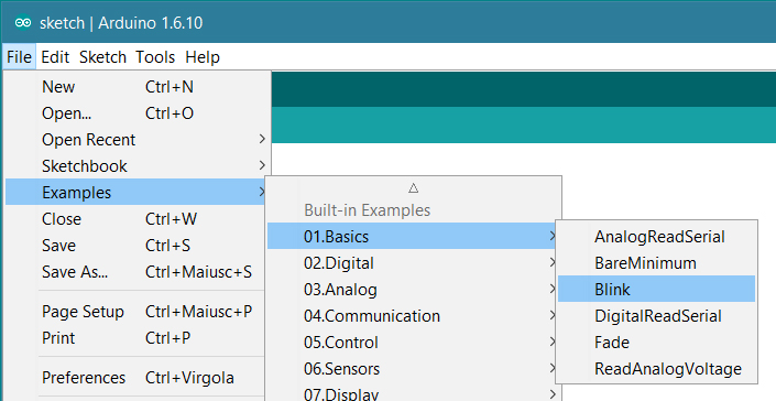
Open the LED blink example sketch: File > Examples >01.Basics > Blink.
Select your board type and port
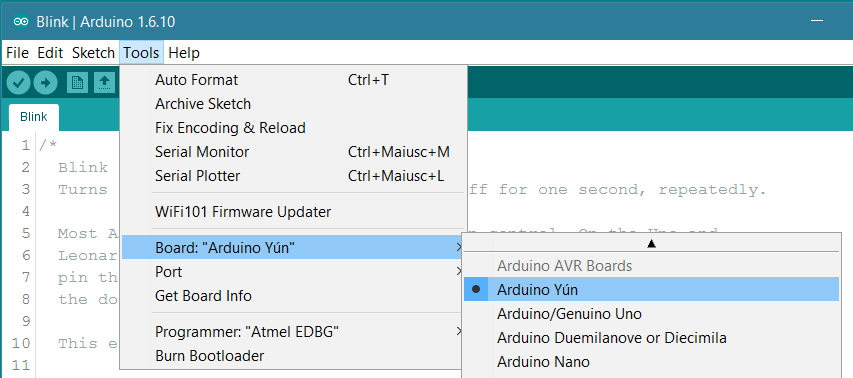
You’ll need to select the entry in the Tools > Board menu that corresponds to your Arduino or Genuino board.
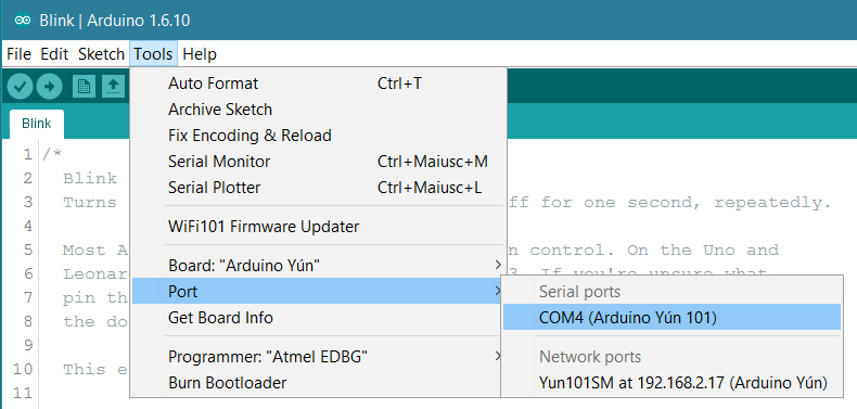
Select the serial device of the board from the Tools | Serial Port menu. This is likely to be COM3 or higher (COM1 and COM2 are usually reserved for hardware serial ports). To find out, you can disconnect your board and re-open the menu; the entry that disappears should be the Arduino or Genuino board. Reconnect the board and select that serial port. When your board is properly configured on WiFi, you will find it in the Port list, as in our screenshot.
Upload the program
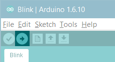
Now, simply click the “Upload” button in the environment. Wait a few seconds - you should see the RX and TX leds on the board flashing. If the upload is successful, the message “Done uploading.” will appear in the status bar.
A few seconds after the upload finishes, you should see the LED(D13) on the board start to blink (in green). If it does, congratulations! You’ve gotten Arduino up-and-running. If you have problems, please see the troubleshooting suggestions.
Program on ATHEROS AR9331 side
Configure Network
The Seeeduino Cloud has a WiFi interface and a LAN port. Either of them has IP address that can be used for internet connection and device management.
1. Wi-Fi AP Mode
When you power ON the Seeeduino Cloud for the first time, there will be an unsecure WiFi network called SeeeduinoCloud-AXXXX shown in wifi connections. You can connect your computer to this network as shown below. Your computer will get an ip of this network 192.168.240.xxx. The Seeeduino Cloud has a default ip address of 192.168.240.1.
2. Wi-Fi STA Mode
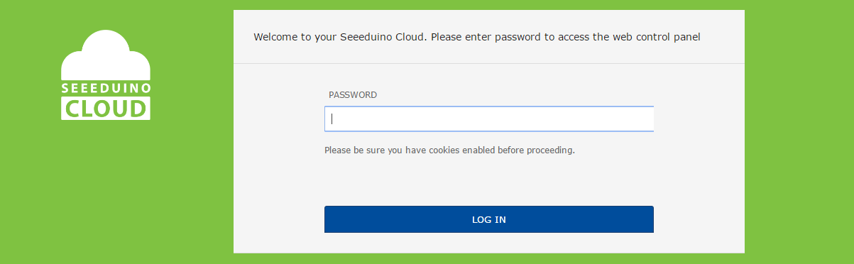
After connect SeeeduinoCloud-AXXXX, type 172.31.255.254 or 192.168.240.1 in browser search box and you will connect to Seeeduino Cloud with web UI. The default password is “seeeduino”, then click LOG IN.
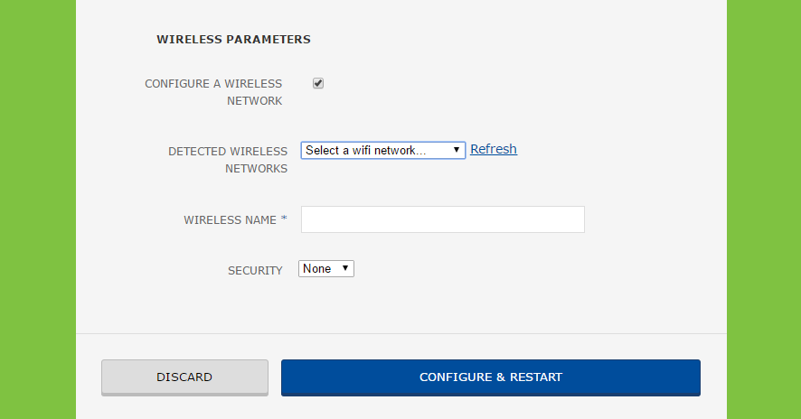
Click “SYSTEM”, select your Wi-Fi network, enter the password and click “CONFIGURE & RESTART”.
3. Onboard Ethernet
When you connect Seeeduino Cloud to a wired network with an ethernet cable, it will try to connect automatically via DHCP. The board will show up on the ports menu just as it would over WiFi.
Terminal
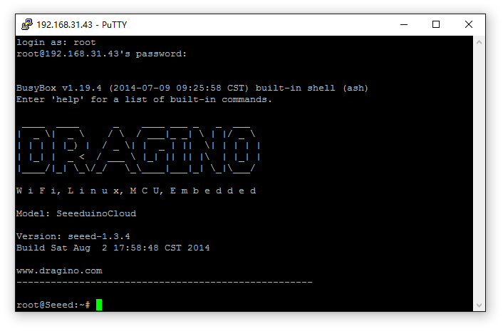
You could access the terminal of Seeeduino Cloud via SSH to Program or configure on ATHEROS AR9331 side.
- Download a SSH client such as putty
- Use the IP address of Seeeduino Cloud and run SSH client.
username: root
password: seeeduino
Yun Bridge Library
The Bridge Library simplifies the communication between the Arduino Board and Dragino HE. Bridge commands from the AVR (Arduino Board) are interpreted by Python on the HE. Its role is to execute programs on the GNU/Linux side when asked by Arduino, provide a shared storage space for sharing data like sensor readings between the Arduino and the Internet * receive commands from the Internet and pass them directly to the Arduino. There are detailed explanations and lots of examples to show how to use Bridge on the Arduino Official Website. Following are some examples that use Bridge Library.
Example 1: Say hello to Linux
This example is a hello test between the Arduino and Seeeduino Cloud. The example can be found on the Arduino IDE–> File –> Examples –> Bridge –> ConsoleRead. A tutorial of this example can be found here. You can see the code below with some additional details to understand it with the Seeeduino Cloud:
#include <Console.h>

String name;

void setup() {
    // Initialize Console and wait for port to open:
    Bridge.begin();
    Console.begin();

    // Wait for Console port to connect
    while (!Console);

    Console.println("Hi, what's your name?");
}

void loop() {
    if (Console.available() > 0) {
        char c = Console.read(); // read the next char received
        // look for the newline character, this is the last character in the string
        if (c == '\n') {
            //print text with the name received
            Console.print("Hi ");
            Console.print(name);
            Console.println("! Nice to meet you!");
            Console.println();
            // Ask again for name and clear the old name
            Console.println("Hi, what's your name?");
            name = "";  // clear the name string
        }
        else {       // if the buffer is empty Cosole.read() returns -1
            name += c; // append the read char from Console to the name string
        }
    }
}
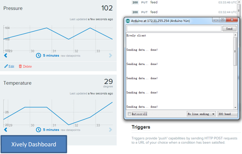
Example 2: Upload data to IoT Server
This example shows how to log data to the public IoT server “Xively”. The example is a modified version (change Serial to Console to fit for different Arduino Board and debug over WiFi) from Arduino IDE–> File –> Examples –> Bridge –> XivelyClient. Tutorial of this example can be referred here. Before uploading the sketch, make sure:
- The Seeeduino Cloud already has internet access.
- Input your FEED ID and API KEY according to the Tutorial. Note, The FEED ID should be within double quotation marks “” .
/*
  Xively sensor client with Strings

 This sketch connects an analog sensor to Xively,
 using an Arduino Yún.

 created 15 March 2010
 updated 27 May 2013
 by Tom Igoe

 http://arduino.cc/en/Tutorial/YunXivelyClient

 */
#include <Process.h>
#include "passwords.h"      // contains my passwords, see below

/*
  NOTE: passwords.h is not included with this repo because it contains my passwords.
 You need to create it for your own version of this application.  To do so, make
 a new tab in Arduino, call it passwords.h, and include the following variables and constants:

 #define APIKEY        "foo"                  // replace your pachube api key here
 #define FEEDID        0000                   // replace your feed ID
 #define USERAGENT     "my-project"           // user agent is the project name
 */

// set up net client info:
const unsigned long postingInterval = 60000;  //delay between updates to xively.com
unsigned long lastRequest = 0;      // when you last made a request
String dataString = "";

void setup() {
    // start serial port:
    Bridge.begin();
    Serial.begin(9600);

    while (!Serial);   // wait for Network Serial to open
    Serial.println("Xively client");

    // Do a first update immediately
    updateData();
    sendData();
    lastRequest = millis();
}

void loop() {
    // get a timestamp so you can calculate reading and sending intervals:
    long now = millis();

    // if the sending interval has passed since your
    // last connection, then connect again and send data:
    if (now - lastRequest >= postingInterval) {
        updateData();
        sendData();
        lastRequest = now;
    }
}

void updateData() {
    // convert the readings to a String to send it:
    dataString = "Temperature,";
    dataString += random(10) + 20;
    // add pressure:
    dataString += "\nPressure,";
    dataString += random(5) + 100;
}

// this method makes a HTTP connection to the server:
void sendData() {
    // form the string for the API header parameter:
    String apiString = "X-ApiKey: ";
    apiString += APIKEY;

    // form the string for the URL parameter:
    String url = "https://api.xively.com/v2/feeds/";
    url += FEEDID;
    url += ".csv";

    // Send the HTTP PUT request

    // Is better to declare the Process here, so when the
    // sendData function finishes the resources are immediately
    // released. Declaring it global works too, BTW.
    Process xively;
    Serial.print("\n\nSending data... ");
    xively.begin("curl");
    xively.addParameter("-k");
    xively.addParameter("--request");
    xively.addParameter("PUT");
    xively.addParameter("--data");
    xively.addParameter(dataString);
    xively.addParameter("--header");
    xively.addParameter(apiString);
    xively.addParameter(url);
    xively.run();
    Serial.println("done!");

    // If there's incoming data from the net connection,
    // send it out the Serial:
    while (xively.available() > 0) {
        char c = xively.read();
        Serial.write(c);
    }
}
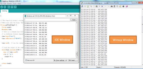
Example 3: Log Data to USB flash
This example shows how to log data to a USB flash. The sketch used in this example is same as here. And the source code can be found there. The Seeeduino Cloud will auto mount the USB flash to directory /mnt/sda1. And the sketch will append the sensor data to the file /mnt/sda1/data/datalog.csv. So make sure there is such a file in the USB flash before running the sketch.
#include <FileIO.h>     //FileIO class allow user to operate Linux file system
#include <Console.h>    //Console class provide the interactive between IDE and Yun Shield
void setup() {
    // Initialize the Console
    Bridge.begin();
    Console.begin();
    FileSystem.begin();
    while(!Console);   // wait for Serial port to connect.
    Console.println("Filesystem datalogger\n");
}
void loop () {
    // make a string that start with a timestamp for assembling the data to log:
    String dataString;
    dataString += getTimeStamp();
    dataString += " , ";
    // read three sensors and append to the string:
    for (int analogPin = 0; analogPin < 3; analogPin++) {
        int sensor = analogRead(analogPin);
        dataString += String(sensor);
        if (analogPin < 2) {
            dataString += ",";    // separate the values with a comma
        }
    }
    // open the file. note that only one file can be open at a time,
    // so you have to close this one before opening another.
    // The USB flash card is mounted at "/mnt/sda1" by default
    File dataFile = FileSystem.open("/mnt/sda1/data/datalog.csv", FILE_APPEND);
    // if the file is available, write to it:
    if (dataFile) {
        dataFile.println(dataString);
        dataFile.close();
        // print to the serial port too:
        Console.println(dataString);
    }
    // if the file isn't open, pop up an error:
    else {
        Console.println("error opening datalog.csv");
    }
    delay(15000);  //Write every 15 seconds
}
// getTimeStamp function return a string with the time stamp
// Yun Shield will call the Linux "date" command and get the time stamp
String getTimeStamp() {
    String result;
    Process time;
    // date is a command line utility to get the date and the time
    // in different formats depending on the additional parameter
    time.begin("date");
    time.addParameter("+%D-%T");   // parameters: D for the complete date mm/dd/yy
    //              T for the time hh:mm:ss
    time.run();   // run the command
    // read the output of the command
    while(time.available()>0) {
        char c = time.read();
        if(c != '\n')
        result += c;
    }
    return result;
}
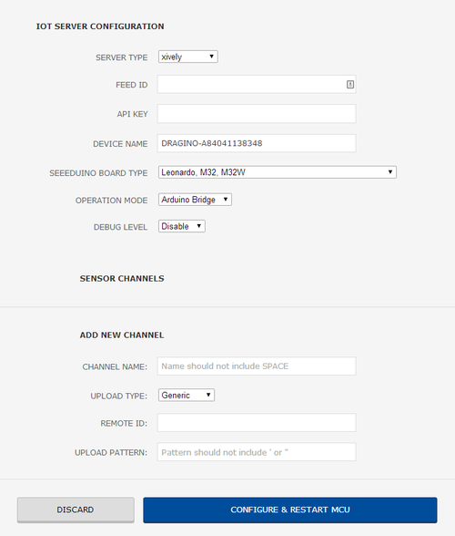
IoT Server Configuration
The IoT Server page allows you to upload data to IoT websites such as Xively while you only need to write sensor data to serial port.
and the sketch is shown below.
/*
  Simulate UART TX Data

 This sketch simulate Temperature and Humidity data to UART.

 To test the pass through feature for different IoT service

 created 25 Apr 2014
 by Dragino Technology Co., Limited

 Reference:
 http://wiki.dragino.com/index.php?title=Xively#Upload_data_to_Xively_use_Pass_Through_Mode

 */
String dataString = "";

void setup() {
    Serial1.begin(115200);
}

void loop() {
    dataString = "temp:";
    dataString += random(10) + 20;
    Serial1.println(dataString);  // upload Temperature data
    delay(20000);
    dataString = "humidity:";
    dataString += random(5) + 70;  // upload humidity data
    Serial1.println(dataString);
    delay(20000);
}
Resources
- Schematic
- Firmware
- References
FAQ
- What is Yun Bridge Library?
Yun Bridge Library is the mechanism used in Arduino Yun for communication between a MPU and a MCU. Seeeduino Cloud supports Yun Bridge Library to make it easy for Arduino users to build their IoT projects.
Help us make it better
Thank you for choosing Seeed. A couple of months ago we initiated a project to improve our documentation system. What you are looking at now is the first edition of the new documentation system. Comparing to the old one, here is the progresses that we made:
- Replaced the old documentation system with a new one that was developed from Mkdocs, a more widely used and cooler tool to develop documentation system.
- Integrated the documentation system with our official website, now you can go to Bazaar and other section like Forum and Community more conveniently.
- Reviewed and rewrote documents for hundreds of products for the system’s first edition, and will continue migrate documents from old wiki to the new one.
An easy-to-use instruction is as important as the product itself. We are expecting this new system will improve your experience when using Seeed’s products. However since this is the first edition, there are still many things need to improve, if you have any suggestions or findings, you are most welcome to submit the amended version as our contributor or give us suggestions in the survey below, Please don’t forget to leave your email address so that we can reply.
Happy hacking
댓글 없음:
댓글 쓰기