Seeeduino v4.2
Introduction
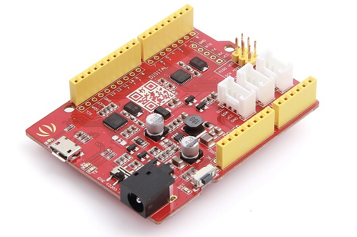
Seeeduino v4 is an Open Source, Arduino-compatible ATmega328 MCU development board. We think Seeeduino v4 is one of the best Arduino derivatives/compatibles available. Seeeduino v4 is feature rich, much more stable, easy-to-use and even good looking.
Seeeduino v4 is based the Arduino UNO bootloader, an ATmega16U2 as a UART-to-USB converter (basically work like an FTDI USB2UART chip). The board comes with an additional set of through-hole pads for all pins. These pads are aligned to 0.1” grid. This makes it easy to solder additional pin-headers to plug into breadboard or create your own attachment/shield with 0.1” dot-matrix general purpose PCBs.
You can program the board via a micro-USB cable. Also, you can power the board via a DC Jack input (7 to 15V DC) is acceptable. There is a switch to choose the system’s supply voltage either 3.3V or 5V, which is very useful if you want to set the system to 3.3V to interact with low voltage sensors.
Finally, the three on-board Grove interfaces can make your board connect to Grove modules easily. Want to make something awesome, maybe just a Seeeduino v4.2 and some Groves is enough.
Version
This document applies to the following version of products:
| Version | Released Date | How to Buy |
|---|---|---|
| Seeeduino V4.0 | Aug 15, 2014 |  |
| Seeeduino V4.2 | Aug 24, 2015 |  |
What’s New in Seeeduino V4.2
There’re many updates from V4.0 to V4.2. Listed below:
- Cancel some pad on the top left corner.
- Change the usb location to middle
- Improve DCDC circuit to get a better performance
- Add an I2C Grove connector
- Change some silkscreen and part location
Application Ideas
- DIY
- IoT and Smart Home
- Robot
- Learning
Here is some funny project for your reference.
| Paper Man | Fingerprint Lock | Monitor Stand |
|---|---|---|
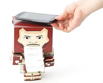 | 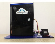 | 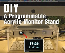 |
| Make it Now | Make it Now | Make it Now |
| Desk Promo | Tiger Machine | Colorful Pyramid |
|---|---|---|
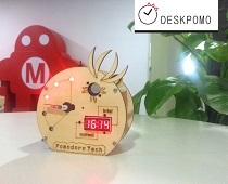 | 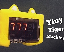 |  |
| Make it Now | Make it Now | Make it Now |
Features
- Fully compatible with Arduino UNO
- ATmega328 microcontroller
- 14 Digital I/O Pins (6 PWM outputs)
- 6 Analog Inputs
- ISP Header
- Arduino UNO-R3 Shield Compatible
- Micro USB programming and power supply
- On-board Grove connectors
- 3.3/5V system operation power switch
- Additional pads aligned to 0.1” grid
Specification
| Item | Value |
|---|---|
| DC Jack Input | 7-12V |
| DC Output Current | |
| 5V Pin | With Micro USB 500mA Max |
| 5V Pin | With DC Jack Power 2000mA Max |
| 3V3 Pin | 500mA Max |
| DC Current per I/O Pin | 40mA |
| Flash Memory | 32 KB |
| RAM | 2 KB |
| EEPROM | 1 KB |
| Clock Speed | 16 MHz |
| Dimension | 68.6mm x 53.4mm |
| Weight | 26g |
Hardware Overview
Note
This part is based on Seeeduino V4.2
The images below show an overview of Seeeduino v4.2 hardware features. The pin-out and alternate functions of various pins of Seeeduino v4.2 are shown in the pin-out diagram. This could be used as a quick reference.
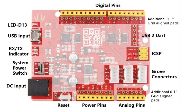
- LED-D13 An LED is connected to D13 pin of the board. This can be used as an on-board LED indicator for programs/sketches.
- USB Input USB Port is used to connect the board to your PC for programming and for powering up. Micro USB is the ubiquitous version of USB, found in most Android phones, and other devices. You probably have dozens of these cables laying around your house.
- RX/TX Indicator The TX and RX LED indicators are connected to TX and RX of USB-to-UART chip. They work automatically, they let you know when the board is sending or receiving data respectively.
- System Power Switch Slide switch is used to change the logic level and operating voltage of the board to either 5V or 3.3V. Nowadays, many new and great sensors are being developed to work only with 3.3V, with other Arduino boards you would need to place a logic level converter between the board and these sensor(s). With the Seeeduino V4 board all you have to do is slide the switch!
- DC Input The DC power jack allows your Seeeduino board to be powered from a wall adapter so that you can supply more power to your project if needed. For example, when using DC motors or other high power devices. The DC input can be 7V-15V.
- Reset This button is conveniently placed on the side to allow you to reset the Seeeduino board even when a shield is placed on top. This is not the case in other Arduino boards where the button is placed on top making it hard to access.
- Power Pins & Analog Pins Just like the extra Digital header pads, these extra connections are something we have personally come to realize people need in their projects, especially the power connections if you want to power more than one sensor/device without the use of a breadboard.
- Grove Connectors SeeedStudio has a variety of sensors/devices that can make use of this I2C or UART connection. In addition, we sell independent Grove connectors to help you make our own sensor connections. The I2C Grove connector is also connected to analog pin A4 and A5 for SDA and SCL respectively if you would like to use those pins instead. The UART Grove connector is connected to digital pins 0 and 1 for RX and TX respectively.
- ICSP This is the ICSP connection for the ATmega328P, it is located in the standard ICSP/SPI position for Arduino Uno, Due, Mega, and Leonardo compatible hardware (e.g. shields) that may use this connector. The SPI pins in this port: MISO, SCK, and MOSI, are also connected to digital pins 12, 13, and 11 respectively just like those of the Arduino Uno.
- USB 2 Uart Pinout of USB-2-Uart. These pads can be used to interact with other UART devices by putting the on-board ATmega328 in reset mode. This makes Seeeduino V4.2 to be used a USB2UART utility board.
- Additional 0.1” Grid aligned header Pads Sometimes it is very convenient to connect a sensor/device to your board directly instead of going through a breadboard, or perhaps you want to solder the sensor directly to the board once you’ve completed your project, or maybe you want to monitor the output of the pins while they’re been used by other devices. In any cases we have added these extra pads to help you along the way. These pads are aligned in 0.1” grid and can conveniently work with general purpose dot-matrix PCBs.
Warning
Take gentle care in handling micro USB socket, or you might break the socket off.
Install the Driver
First of all, you need to:
- Get a Micro-USB cable
- You need a Micro-USB cable first; the data cable of an Android Phone will do fine. If you can’t find one, you can buy one here.
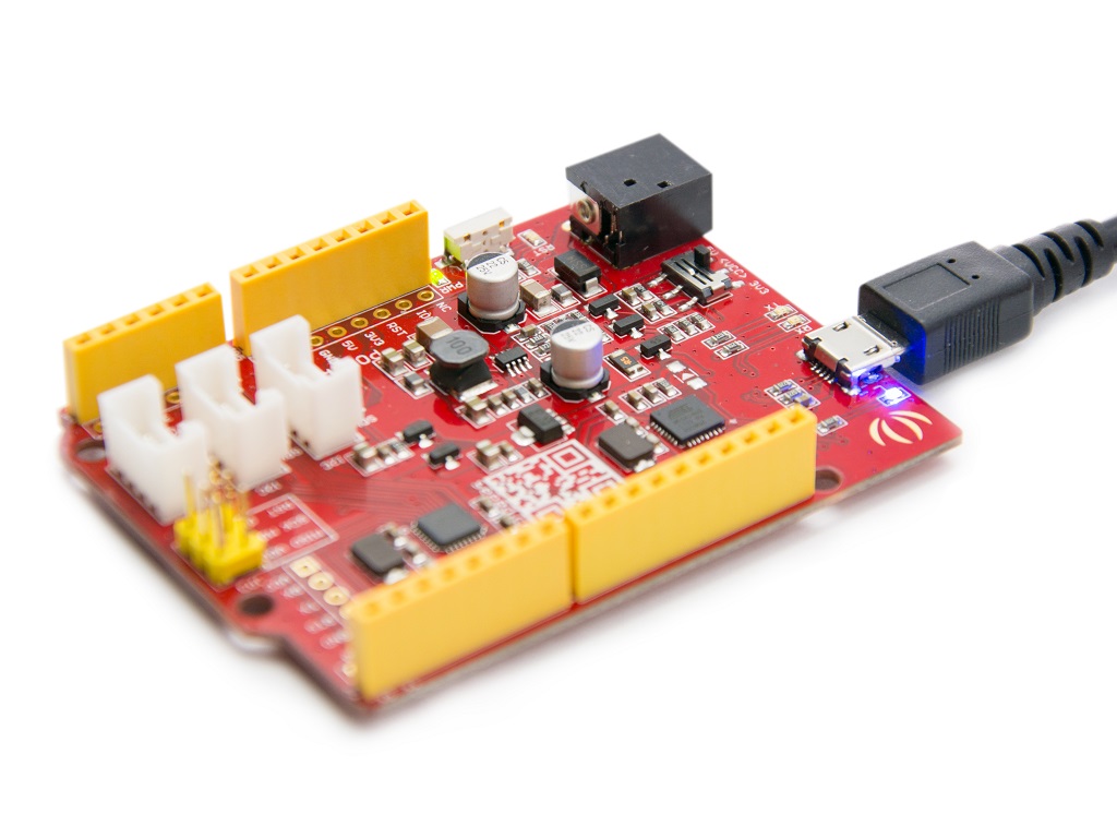
- Connect the board
- The Seeeduino V4.2 automatically draw power from either the USB connection to the computer or an external power supply. Connect the Arduino board to your computer using the USB cable. The green power LED (labelled PWR) should go on.
For Windows
Note
This drive is available for Windows XP, Windows Vista, Windows 7, Windows 8/8.1 and Windows 10.

- Plug in your board and wait for Windows to begin its driver installation process. After a few moments, the process will fail, despite best efforts.
- Click on the Start Menu, and open up the Control Panel.
- While in the Control Panel, navigate to System and Security. Next, click on System. Once the System window is up, open the Device Manager.
- Look under Ports (COM & LPT). You should find an open port named “Seeeduino v4”. If there is no COM & LPT section, look under “Other Devices” for “Unknown Device”.
- Right click on the “Seeeduino v4” port and choose the “Update Driver Software” option.
- Next, choose the “Browse my computer for Driver software” option.
- Finally, navigate to and select the driver file named “SeeeduinoV4.inf”
- Windows will finish up the driver installation from there.
For Mac OSX
You don’t need to install any drivers.
Getting Started
Note
This part is based on Arduino 1.6.9 under Windows 10.
First of all, you need to Install an Arduino Software.

Launch the Arduino application
Double-click the Arduino application (arduino.exe) you have previously downloaded.
Note
If the Arduino Software loads in a different language, you can change it in the preferences dialog. See the Arduino Software (IDE) page for details.
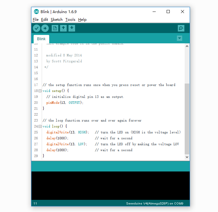
Open the Blink example
Open the LED blink example sketch: File > Examples >01.Basics > Blink.
Add Seeeduino to your Arduino IDE
There is no Seeeduino V4 option in the boards of your Arduino IDE, click on How to Add Seeed boards to Arduino IDE for the instruction.
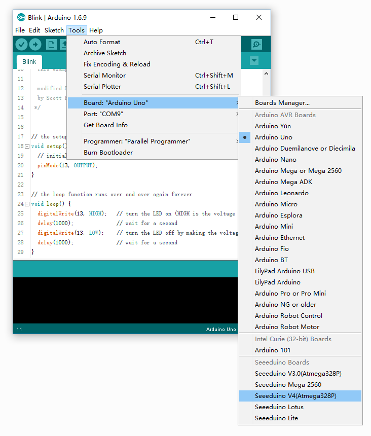
Select your board
You’ll need to select the entry in the Tools > Board menu that corresponds to your Arduino. Selecting a Seeeduino V4.
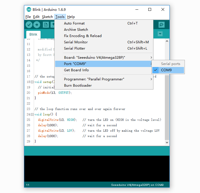
Select your serial port
Select the serial device of the Arduino board from the Tools | Serial Port menu. This is likely to be COM3 or higher (COM1 and COM2 are usually reserved for hardware serial ports). To find out, you can disconnect your Arduino board and re-open the menu; the entry that disappears should be the Arduino board. Reconnect the board and select that serial port.
Note
On the Mac, this should be something with /dev/tty.USBmodem.
Upload the program
Now, simply click the “Upload” button in the environment. Wait a few seconds - you should see the RX and TX LED indicators on the board flashing. If the upload is successful, the message “Done uploading.” will appear in the status bar.

A few seconds after the upload finishes, you should see the pin 13 (L) LED on the board start to blink (in orange). If it does, congratulations! You’ve gotten Arduino up-and-running. If you have problems, please see the troubleshooting suggestions.
Getting Started on Linux
For using on Linux, please go to Installing Arduino on Linux
Resources
- Schematic
- Datasheet
- References
FAQ
Q1. What’s the difference between Arduino UNO and Seeeduino V4
Seeeduino V4 is fully compatible with Arduino UNO. The mainly difference list below:
- Use a micro USB to power and program the board
- 3 on-board Grove connector
- 3.3/5V system power switch
- DCDC circuit instead of LDO, more efficiency
- Others circuit improve
Q2. I can’t upload my sketch to Seeeduino V4
Please check,
- If the Power LED on
- If you choose the right Port and Board (Seeeduino V4)
- Close and reopen Arduino IDE and try again
Q3. Where can I find technical support if I have some other issue.
You can post a question to Seeed Forum or send an email to techsupport@seeed.cc.
Help us make it better
Thank you for choosing Seeed. A couple of months ago we initiated a project to improve our documentation system. What you are looking at now is the first edition of the new documentation system. Comparing to the old one, here is the progresses that we made:
- Replaced the old documentation system with a new one that was developed from Mkdocs, a more widely used and cooler tool to develop documentation system.
- Integrated the documentation system with our official website, now you can go to Bazaar and other section like Forum and Community more conveniently.
- Reviewed and rewrote documents for hundreds of products for the system’s first edition, and will continue migrate documents from old wiki to the new one.
An easy-to-use instruction is as important as the product itself. We are expecting this new system will improve your experience when using Seeed’s products. However since this is the first edition, there are still many things need to improve, if you have any suggestions or findings, you are most welcome to submit the amended version as our contributor or give us suggestions in the survey below, Please don’t forget to leave your email address so that we can reply.
Happy hacking
댓글 없음:
댓글 쓰기