Seeeduino Stalker V3.1
Introduction
Maybe you are very familiar with the Seeeduino stalker series, or maybe you are totally new to this feature rich Wireless Sensor Network Node. No matter what situation you are in, if you are going to make an outdoor data-logging application, you will find that Seeeduino Stalker is the best board.
The main purpose of creating this series is to create an X-bee carrier board so that users can make outdoor application more conveniently. Ever since the first version be released in 2009, Seeeders has been continuously collecting feedback from users and kept upgrading the board. there are 6 versions ever existed during the past 7 years, this summer we are excited to release the most updated member of the Seeeduino stalker family----Seeeduino Stalker V3.1.
Seeeduino Stalker V3.1 is not just a simple update of V3.0.The main surprise you’ll find about the board is impressively low power consumption, in sleep mode, the output current of the whole board will be as low as 100uA,This is an upgrade truly derived from users feedback.(we really care about your opinion).let’s see how we achieve it.
Version Track
What’s new in Seeeduino Stalker V3.1
Improve Power Management
In V3.1, when MCU is in sleep mode, all other power supplement, including Bee area port, 3.3v port, VCC can be cut off manually, so that power can really be saved.
Other Changes
There is a toggle switch added to X-bee area, which allows you to select either the hardware serial port or software serial port base on what you want to connect.
We also added 2 toggle switch on RTC circuitry corresponding 2 INT pin of MCU, so that users can easily choose which INT pin to be connected with RTC INT port then activate MCU.
Features
- Arduino UNO compatible pinout with Arduino Fio bootloader
- Lipo battery manager IC and Solar charge input(jst2.0 connector)
- Onboard Real Time Clock chip DS1337S (Socket for a CR1220 coin cell, which acts as a backup power source for RTC)
- Serial interface with DTR for auto reset during programming when operating in standalone mode.
- microSD card socket
- Grove connector (operation voltage is selectable: 5.0V or 3.3V)
- Reset buttons for both XBee Modules and ATMega328P
- Bee series socket 2*10 pin 2.0mm pitch
Specification
| Parameter | Value |
|---|---|
| Micro Controller | Atmega328P |
| Clock Speed | 8 MHz |
| I/O Voltage | 3.3V |
| RTC | DS1337S |
| Board for Arduino IDE | Arduino Pro or Pro Mini (3.3v , 8 MHz)w/ATmega328 |
| Power Supply | 3.7v LiPo Battery, Use 5VDC solar panel for charging the battery |
| Power Connector | 2 pin JST/ USB |
| Connectivity | I2C, UART, SPI |
| SD Card | micro SD card |
| Open Circuit Current | 6 mA max |
| Charging Current | 300mA |
| Maximum Current on 3.3v port | 800mA |
| Size of PCB | 86.74mm x 60.96mm |
Application Ideas
- Wireless Sensor Network (using XBee bought separately)
- GPS Logging (using GPSBee bought separately)
- Data Acquisition System capable of communicating with an App running on iPhone/Android Phone (using BluetoothBee bought separately).
- RF Remote Control (using RFBee bought separately).
- As a simple standalone Arduino compatible physical computing platform.
Hardware Overview
Overview
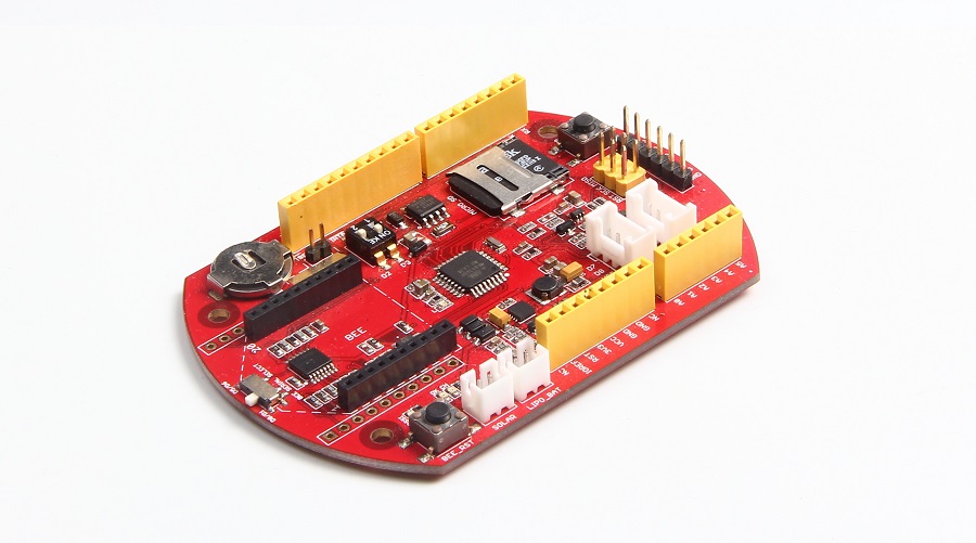
Seeeduino Stalker V3.1 is an application board with rich function. RTC, Lipo battery connector, Bee socket and SD card socket etc. The below overview image will introduce each part of the board to help you to know the board better.
| NAME | FUNCTION |
|---|---|
| RTC BATTERY | Cell battery to power DS1337S |
| RTC_INT | RTC interrupt switch |
| Bee Serial Select | Bee RX/TX pin select, you can select D0/D1 or D6/D7 |
| Bee Socket | Insert a Bee |
| CHARGE STATUS LED | OK: a green led, on while charge done. CH: a red led, on while charging |
| BEE RST | Reset the Bee |
| SOLAR | Solar input to charge the battery, input 4.5~6V |
| LIPO | lipo battery input, 3.7V |
| L | A LED connected to D13, can be acted as a monitor |
| GROVE2 | Grove port, connect to I2C |
| GROVE1 | Grove port, connect to D7/8 |
| PROGRAM | Programming port, connect to a UartSBee here |
| RST | Reset the Atmega328P |
| SD CARD | A micro SD Card socket |
Pinmap
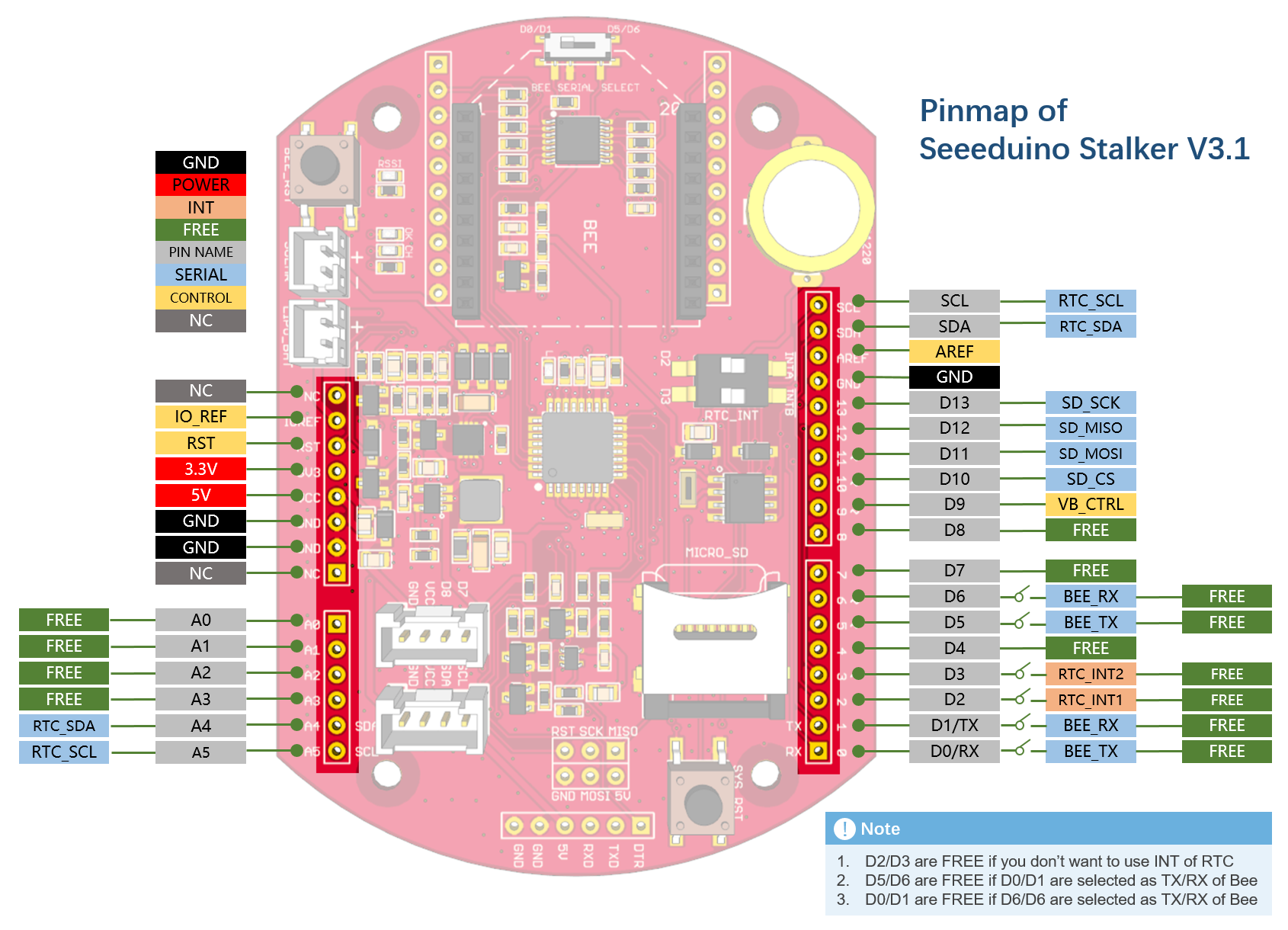
Seeeduino Stalker V3.1 is compatible with Arduino, there’re many Analog pins, Digital Pin as well as Serial pins available to make your own application. Below pin map image will help you to decided which pin are free or not as well as the pin used.
Get Started
If this is your first time to program with a Seeeduino Stalker. You can follow the below steps to getting started. Before we start, make sure you have the below things on hand:
| Seeeduino Stalker V3.1 | UartSBee V4 | Mini USB Cable | 6pin Cable |
|---|---|---|---|
 |  |  |  |
| GET ONE NOW | GET ONE NOW | GET ONE NOW | GET ONE NOW |
Note
UartSBee V4, Mini USB Cable and 6pin cable are not included.
STEP1: Connection
Firstly connect Staler to UartSBee via the 6pin jumper wire, then connect UartSBee to a PC via the mini USB cable.
| Seeeduino Stalker | UartSBee V4 |
|---|---|
| DTR | DTR |
| TXD | RXD |
| RXD | TXD |
| 5V | VCC |
| GND | GND |
Note
The power switch on UartSBee V4 put to 5V
STEP2: UartSBee and the Driver
UartSBee is a USB to Serial UART interface which is based on FT232RL from FDTI. Click to download the driver for the board.
In our case, it will perform three functions:
- To program the Seeeduino Stalker.
- To communicate with Seeeduino Stalker.
- Provide power (from USB power of PC) to Seeeduino Stalker (including any peripherals connected to it).
STEP3: Arduino IDE
Seeeduino Stalker is an Arduino compatible board that with rich function. If you don’t have an Arduino IDE, you need to download the latest Arduino software to program the board.
STEP4: Add Seeeduino Stalker to your Arduino IDE
There is no Seeeduino Stalker option in the boards of your Arduino IDE, click on How to Add Seeed boards to Arduino IDE for the instruction.
STEP5: Blink
Here we will update a simple code to Stalker. Open your Arduino IDE, open File > Examples > Basics > Blink
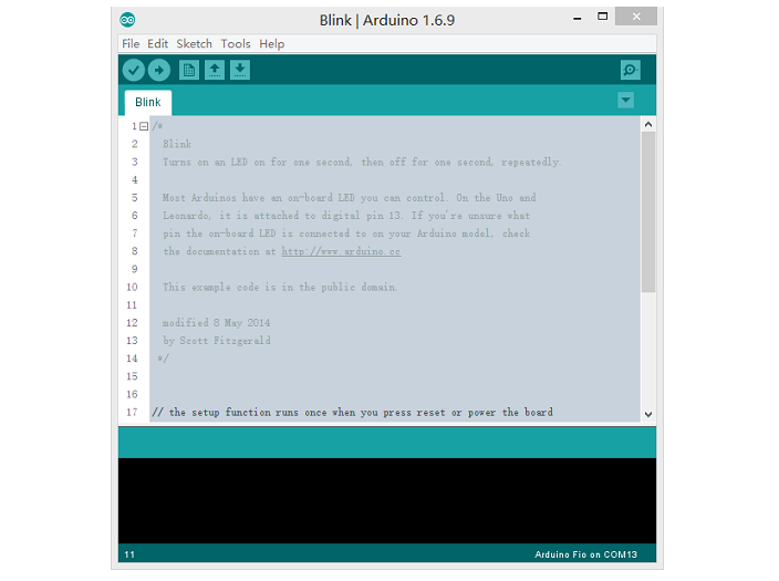
Then click on the Upload button, seconds later after the uploading is done, check L on the board, it will blink at the frequency of 1s.
Examples for Stalker V3.1
There are many examples for Seeeduino Stalker V3.1, which is consist of:
- Example of reading the voltage of battery
- Example of reading the status of charging
- Example of data log
- RTC library and some examples
- Sleep related function
RTC
There’s a on-board DS1307S with a 3V cell battery, which can hold the time for more that 3 years even there’s no power supply to the board. The library of DS1307S is included at the sketch of Stalker.
Adjust Date/Time
Open Arduino IDE, then File > Sketchbook > RTC > Adjust, then set the current date/time using the DateTime Class object dt in the example:
DateTime dt(year, month, date, hour, min, sec, week-day(starts from 0 and goes to 6));
Ex:- DateTime dt(2015, 10, 1, 11, 43, 0, 4);
Compile and upload to Stalker, then time is set.
Get Current Date/Time
Open Arduino IDE, then File > Sketchbook > RTC > Now, The current date/time is read from DS1337 using RTC.now() function.
Ex:- DateTime now = RTC.now();
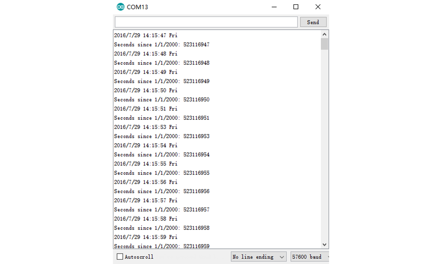
Compile and upload to Stalker, and open the Serial monitor, you will get the date and time display:
DS1337 Interrupts Example
This example is a demonstration of interrupt detection from DS1337 INT output. This feature is useful for data-logger functionality where the MCU is put to sleep mode when not in use and DS1337 INT wakes up the CPU periodically. This extends battery power. The complete operation is documented in the code.
There’re 2 INT output from DS1337, INTA (connect to D2) and INTB (connect to D3). There’s a switch to connect INTA/INTB and D2/D3, if you don’t need the interrupt, you can just close the switch and save 1 or 2 I/O. Switch as below:
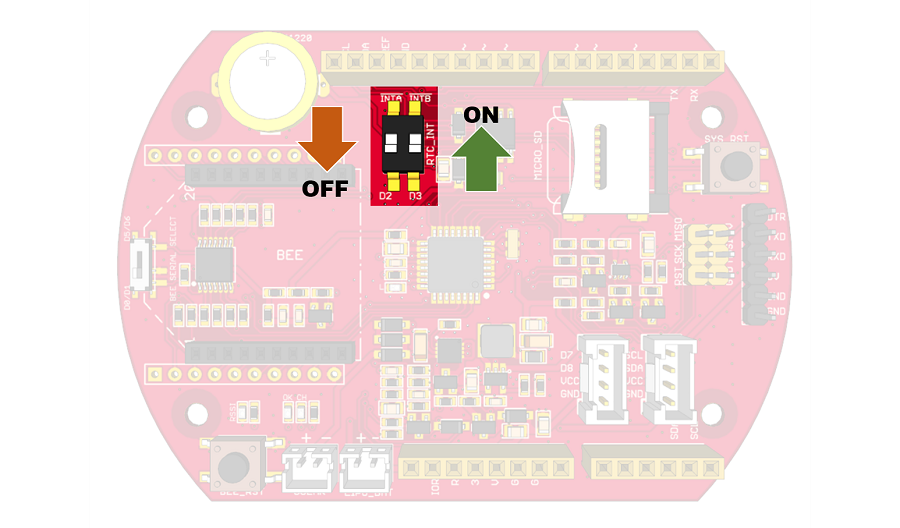
Open Arduino IDE, then File > Sketchbook > RTC > interrupts, this example will generate an interrupt every minutes. If you need other type of alarm, please refer to the code.
SD Card
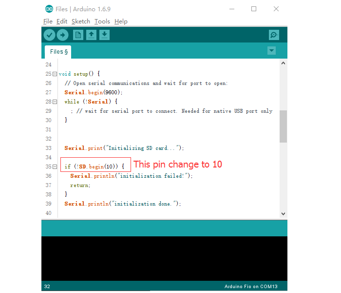
There’s a micro SD card socket which you can insert a micro SD card to store some data. Stalker read/write the SD card via SPI interface. There’re enough examples to operate a SD by using the SD library inside Arduino IDE. Open your Arduino IDE, File > Examples > SD, you will get many examples.
Note
The CS pin is connected to D10 of Stalker, so you need to change the CS pin into D10 at the examples.
Power Manager
There’s Lipo battery manage circuit built in Stalker. There are two useful function supply at the sketch.
Read the voltage of Lipo Battery:
Open Arduino IDE, File > Sketchbook > ReadBattery to open the example.
The voltage of the battery is related to the battery capacity. Below is a reference, but please know that it’s not for every battery, for a certain battery, the data may a little different.
Capacity(%)
|
100%
|
80%
|
60%
|
40%
|
20%
|
0%
|
Voltage(V)
|
4.20
|
4.00
|
3.87
|
3.79
|
3.73
|
3.00
|
Open Arduino IdE, File > Sketchbook > ReadChageStatus to open the examples. This function will return 3 status:GET Charge Status
0: No batter insert
1: Charging
2: Charge done
Bees
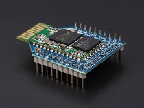
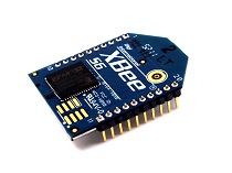
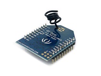
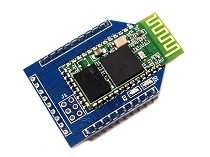
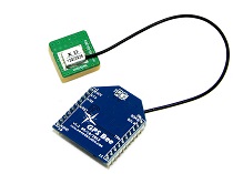
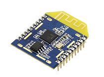
Bees are a series of modules that consist of rich function. Such as Wi-Fi, BLE, GPS as well as RF etc. With an XBee, Stalker can act as a node that with communication. A Stalker talk to another Stalker is no longer impossible. If you need more details about the Bees, below is some reference.
| Bluetooth Bee | XBee Wi-Fi PCB Antenna | RFbee V1.1 |
|---|---|---|
 |  |  |
| GET ONE NOW | GET ONE NOW | GET ONE NOW |
| Bluetooth Bee - Standalone | GPS Bee kit | Mesh Bee |
|---|---|---|
 |  |  |
| GET ONE NOW | GET ONE NOW | GET ONE NOW |
Note
- You need to select the Serial pin for a Bee, D0/D1 and D5/D6 is available. Please refer to Hardware Overview get more info.
- D9 is controlling the power of Vcc of Bee socket, if you need power to a Bee, you should make D9 HIGH: digitalWrite(9, HIGH), and don’t forget to pinMode(9, OUTPUT) in the Setup.
Data Logger Example
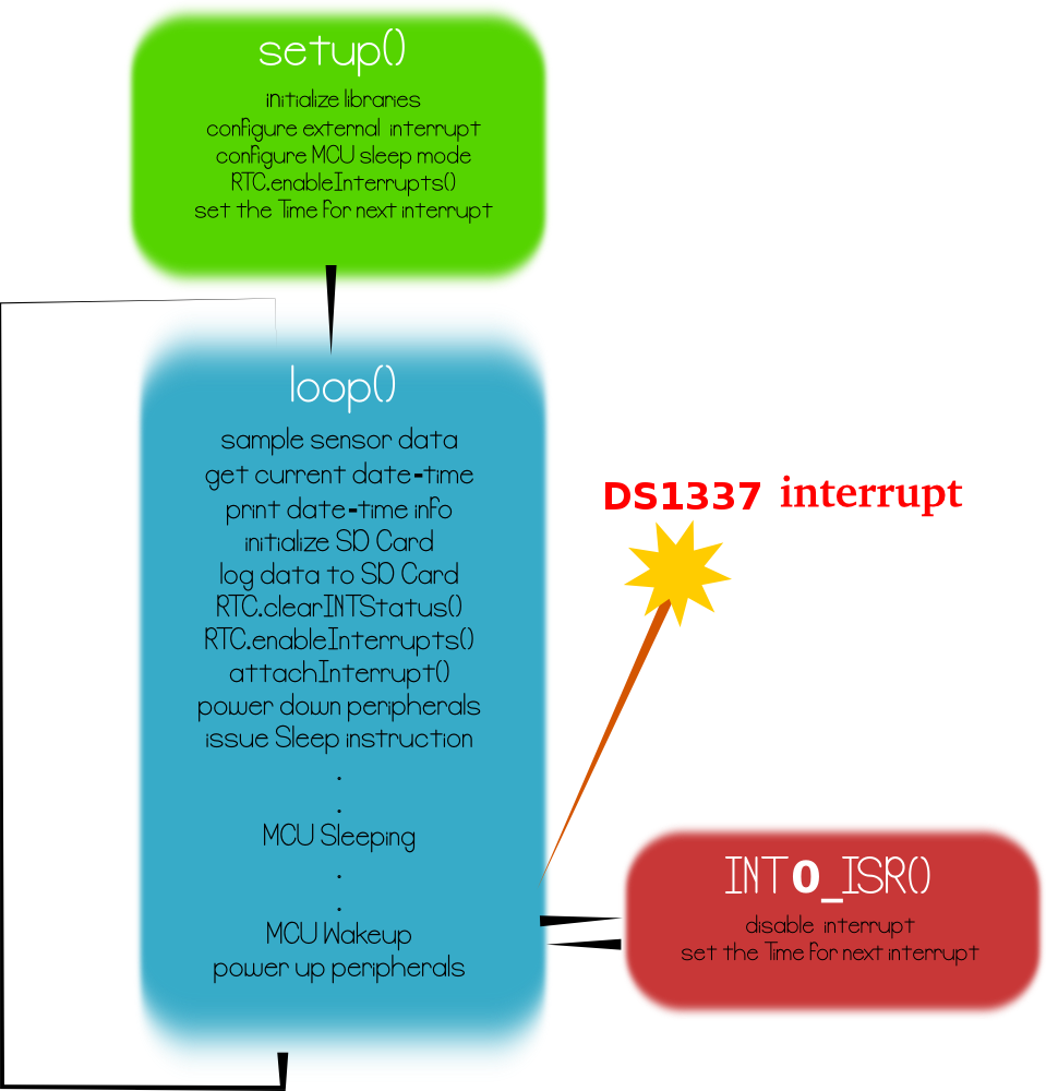
The principal application of Seeeduino Stalker v3.0 is data-logging of sensor signal like battery voltage, etc. along with the time-stamp. This sketch puts the MCU in sleep mode when not performing data sampling / logging operation. The complete implementation is documented very well in the code.
Open Arduino IDE, File > Sketchbook > StalkerV30_DataLogger_10Sec to open the example. - This sketch logs battery voltage data to SD card configured by RTC.enableInterrupts(h, m, s) function. - The periodicity is provided using h, m and s. Once an interrupt is detected, the next interrupt time is updated by advancing the h, m and s value. The DateTime Class comes handy for this. - ex:- interruptTime = DateTime (interruptTime.get() + interruptInterval); //decide the time for next interrupt - This sketch also produces verbose output i.e the various events happening inside MCU are displayed in serial terminal.
Resources
Schematic * Schematic in Eagle * Schematic in PDF
FAQ
Here are some questions that we usually received from new users. If you have any other issues when you are using Seeeduino Stalker V3.1, welcome to the Community of Arduino where there are many professional users waiting to give you advices and also many advanced users providing plenty of ideas on how to use this products!
Q1: The RTC is reset to the original time when power off and on again.
There’s a cell battery to power the RTC when there’s no power from the system. The cell battery is supposed to last at least 3 years. You can check if the cell battery run off.
Q2: I can’t upload sketch to Stalker V3.1
Firstly, check if your USB-UART connected to Stalker right, then check if you select the right port number and board(Arduino Fio or Arduino Arduino Pro or Pro Mini (3.3v , 8 MHz)w/ATmega328). Finaly, if you had inserted a Bee on the socket and the RX/TX is selected to D0/D1, you should take the bee off when uploading the skteck.
Q3: The RTC interrupt demo is not work, I can’t get any interrupt.
Firstly, check if you set the alarm time right, and don’t forget to put the RTC_INT switch to the right side.
Q4: The solar panel can’t charge the lipo battery.
Make sure your solar panel is able to supple 4.5~6V voltage.
Help us make it better
Thank you for choosing Seeed. A couple of months ago we initiated a project to improve our documentation system. What you are looking at now is the first edition of the new documentation system. Comparing to the old one, here is the progresses that we made:
- Replaced the old documentation system with a new one that was developed from Mkdocs, a more widely used and cooler tool to develop documentation system.
- Integrated the documentation system with our official website, now you can go to Bazaar and other section like Forum and Community more conveniently.
- Reviewed and rewrote documents for hundreds of products for the system’s first edition, and will continue migrate documents from old wiki to the new one.
An easy-to-use instruction is as important as the product itself. We are expecting this new system will improve your experience when using Seeed’s products. However since this is the first edition, there are still many things need to improve, if you have any suggestions or findings, you are most welcome to submit the amended version as our contributor or give us suggestions in the survey below, Please don’t forget to leave your email address so that we can reply.
Happy hacking



댓글 없음:
댓글 쓰기