Note added 28.01.2016 The ABC app is a simple app that I first created to allow me to monitor Arduino pins and to give me basic control functions. It isn’t designed for complex control. I have received many comments and suggestions about the ABC app and as a result I am now working on ABC II. This will be a new app rather than an upgrade and will feature better control functions. It is also being designed around the function rather than the Arduino pin. Not sure when it will be ready though.
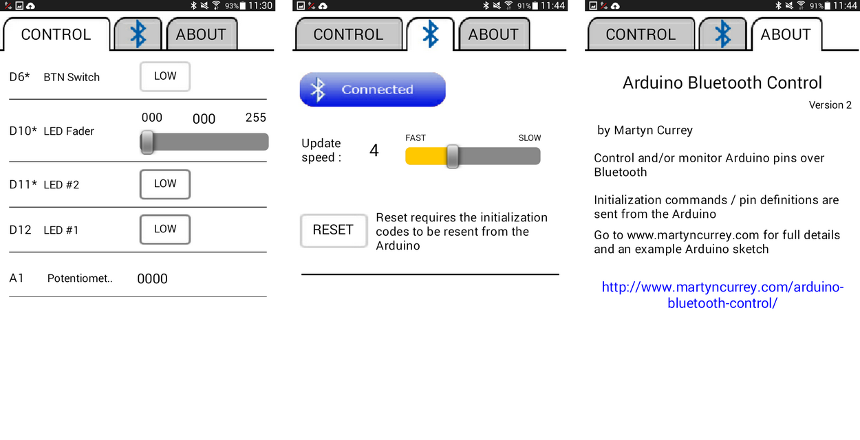
Arduino Bluetooth Control is a simple to use Android app for controlling and/or monitoring Arduino pins over Bluetooth. The app is self contained and all initialization is done from the Arduino sketch. It is designed around Arduino pins rather than control function.
24.10.2015 Now updated to version 2. Added facility for renaming the pin descriptions and the app now has better error reporting for bad initialization commands
07.12.2015 Update to the sketches. I was checking the elapsed time incorrectly. Took me longer than it should have to spot it.
14.02.2016 Updated to version 3. The app now sends a <RESET> code when the RESET button is clicked. This allows the Arduino to detect the app reset and automatically resend the initiation commands. See below for an example sketch.
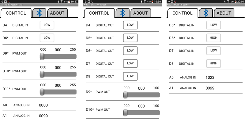
Different configurations Only the pins you are using (have initialized) are displayed.
There are 3 kinds of pin: – Digital Pins – PWM Pins – Analogue Pins
Digital Pins
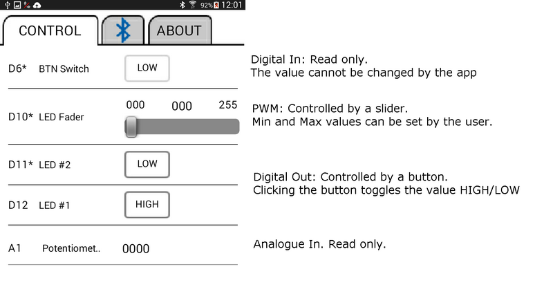
– Digital pins range from D2 to D12. – Digital pins can be input or output. – The value can be set to HIGH or LOW. – The pin state can be controlled by the Arduino and the value displayed by the Android app. – The pin state can be controlled by the Android app.
PWM Pins
– The PWM pins are; D3, D5, D6,D9, D10, and D11 – PWN pins are output only. – The PWM Pin value is controlled by a slider in the Android app. – The minimum and maximum values can be set for each pin. – The smallest minimum is 0. – The largest maximum is 255.
Analogue Pins
– The analogue pins are A0 to A5. – Analogue pins are input only. – The value, from 0 to 1023, is displayed in the Android app.
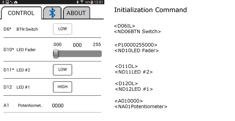
Initialization Commands
The Arduino sends initialization commands to the Android app and this means how the app displays a pin depends on the initialization command sent from the Arduino.
Examples of initialization commands
<D04IL> – Initialize pin D4 for digital input, start value LOW <P10000255041> – Initialize pin D10 for PWN. Min value is 0. Max value is 255. Start value is 41. <D11OH> – Initialize pin D11 for digital output, start value HIGH <D12OH> – Initialize pin D12 for digital output, start value HIGH <A010102> – Initialize pin A1 for analogue in. Start value is 102.
Initialization Commands For Digital Pins
The initialization command for a digital pin is 5 characters (not including the start and end markers). The 1st character is the pin type. D for digital The 2nd and 3rd characters are the pin number. The pin number always uses 2 digits. The 4th character defines if the pin is input or output. I for input. O for output. The final character is the start value. This is the value displayed in the Android app when it first starts, not the actual value of the pin. H for high. L for LOW.
<D06OL> D – pin type. D for digital 06 – the pin number O – Input or output. O for output L – starting value. L for LOW
<D12DIH> D – digital 12 – the pin number I = input H = Starting value of HIGH
Initialization Commands For PWM Pins
The initialization commands for PWM pins are 12 characters long not including the start and end markers. The 1st character is the pin type. P for PWM The 2nd and 3rd characters are the pin number. The pin number always uses 2 digits. The 4th, 5th and 6th characters are the minimum value for the slider. 000 to 255. The 7th, 8th and 9th characters are the maximum value for the slider. 000 to 255. The 10th, 11th and 12th characters are the starting value of the slider. 000 to 255.
<P10000255000> P – pin type. P fop PWM 10 – the pin number 000 – the minimum value 255 – the maximum value 000 – the starting value
<P05000100050> P – PWM 05 – the pin number 000 – the minmium value 100 – the maximum value 050 – the start value
Initialization Commands For Analogue Pins
The initialization command for analogue pins are 7 characters long not including the start and end markers. The 1st character is the pin type. A for Analogue. The 2nd and 3rd characters are the pin number. The pin number always uses 2 digits. The 3rd, 4th, 5th and 6th characters are the starting value displayed in the Android app.
<A011023> A – analogue 01 – the pin number 1023 – the starting value to be displayed by the Android app.
Pin Description / Name Command
The default pin descriptions are: – Digital in – Digital out – Analog in – PWM out
These can be changed using the “Name” command.
<ND06LED> N – for Name D06 – the pin LED – the name or description you wish to give to the pin
All pins have a default description which is applied when the pin is initialized. If you initialize a pin after changing its name, the given name will be over written by the default name.
Number of Commands Command
The final command is the “Number of commands” command. This is used by the Android app to check whether or not it has received all the initialization commands correctly. The command is C followed by the number of commands.
<C7> C – Number of commands (count) 7 – the number of commands not including itself. The count command is used to check that all commands have been received by the app. If the app does not receive the number of commands specified by the count command then an error message will be displayed.
The number is the number of commands not including the “Number of commands” command.
After the app has been set up you can send and receive pin values. This is done via pin data commands
If an incorrect command is received by the Android app an error message will be displayed and the command will be ignored. If the app does not display a pin check the initialization commands for errors.
If you reset the Arduino while the Android app is running you will also need to reset the app. The app will continue to run but the pin values will not be updated. Either restart the app or click the reset button on the Bluetooth page.
Pin Data Commands
There are 2 types of pin data: 1. Those sent from the Arduino to the Android app. 2. Those sent from the app to the Arduino.
Sending data from the Arduino to the Android app.
There are 2 types of pin data that can be sent from the Arduino 1. Digital Pin Data 2. Analogue Pin Data
Pin data commands sent from the Arduino use [ and ] as start and end markers.
Digital pins can be either HIGH or LOW. The command is shortened to H or L. For digital pins the command is basically the pin number and the status. [D04H] – pin D4 is HIGH [D04L] – pin D4 is LOW
The commands are then sent to the Android app with:
Analogue pins can have a value from 0 to 1023. The value should be converted to a string before sending to the app. For analogue pins the command is the pin number plus the value sent as a string. [A010000] A01 – Analogue pin 1 Value = 0000
[A021023] A02 – Analogue pin 2 Value = 1023
The command is sent to the Android app in the same way as the digital command:
BTserial.print("[A011023]");
Note that the value is always 4 digits.
Receiving data on the Arduino from the the Android app
There are 2 types of data command that can be received from the Android app. 1. Digital pin data 2. PWM pin data
Digital pin data
When a digital pin button is clicked in the Android app either a HIGH command or a LOW command is sent to the Arduino. The pin data command consists of the pin number plus the value, H for HIGH. L for LOW.
<D12H> – set pin D12 to HIGH <D12L> – set pin D12 to LOW It is up to the sketch to interpret the commands and act accordingly. IE actually set the pin HIGH or LOW using digitalWrite().
PWM pin data
PWN values can be between 0 and 255 (unless you have set different limits) and the command is the pin number plus the value: <P10000> – set pin D10 to an output of 0 <P10255> – set pin D10 to an output of 255 Remember that the commands do not do anything unless you actually write the value to the pin using analogWrite();
The received command is stored in the receivedChars global variable and you will need to check this to see what the pin number is and what the value is. Note that the start and end markers are stripped away so receivedChars contains only the actual command. P10000 P10255
The value is always 3 digits.
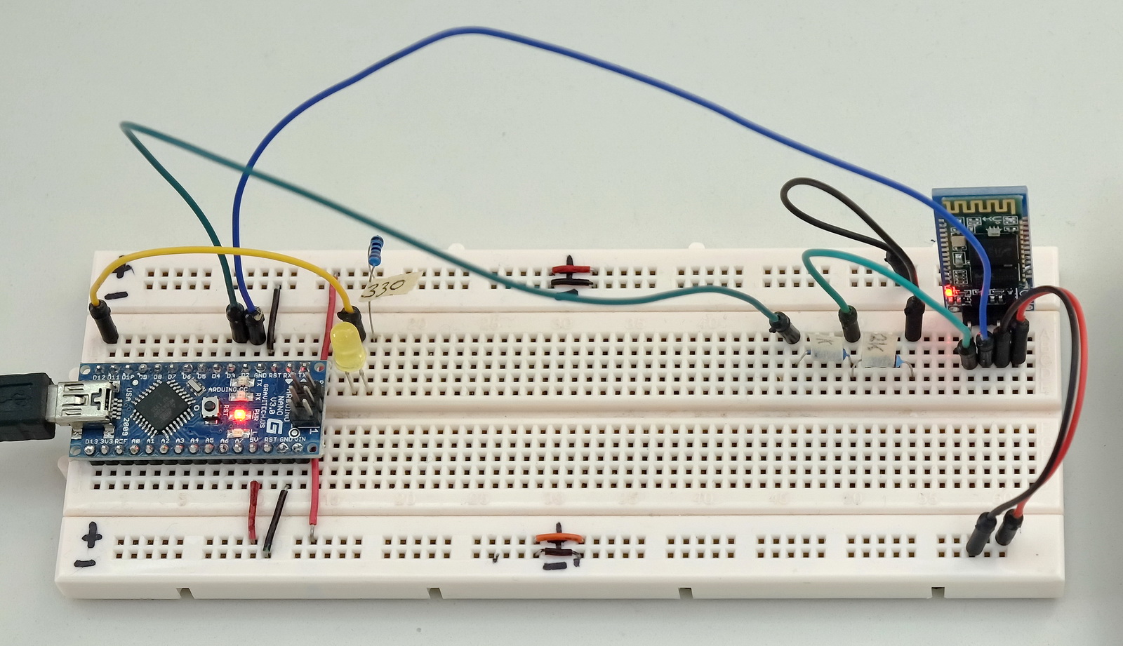
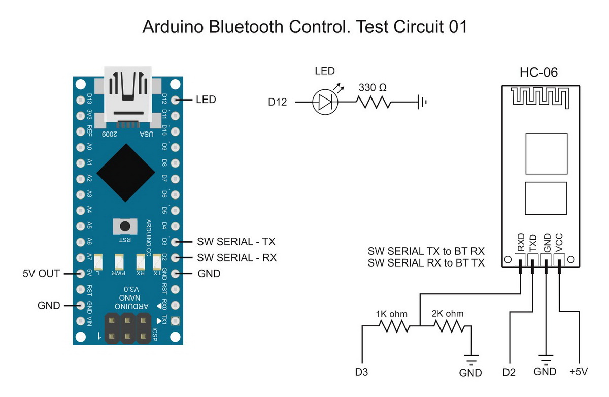
Example 1: Turning an LED on and off
This example uses a single LED on Pin 12. The LEd is controlled via the Android app.
Test Circuit 01. Single LED
The bluetooth module is a HC-06 set for 9600 baud rate. You can use different baud rates if you wish. Match the baud rate in the sketch with the baud rate of your Bluetooth device. A HC-05 can be used as well.
Example 01. Controlling a single LED
There are 2 parts to setting up the pins in the sketch. 1. Set the pin function 2. Send the initialization command
Set the pin function
This is the regular Arduino pin set up.
// Set the LED pin to output and set LOW
pinMode(12, OUTPUT);
digitalWrite(12,LOW);
Send the initialization command
Send the commands to the Android app. The commands tell the app which pins are input and which pins are output. The initialization commands start with a <START> command and end with an <END> commands
Pin 12 is set to digital out with an initial value of LOW.
BTserial.print("<C1>");
C1 is the number of commands (not including iteself in the count) and is used as a check by the app to see if all commands were received correctly.
The Android app counts the number of initialization commands it receives and if this total does not match the total number of commands initialization commands (C1) an error message is displayed. The number of commands does not include the <START> and <END> markers.
On start up, the sketch keeps sending the initialization commands until it receives an “OK” reply from the Android app. Once a reply is received the app starts sending and receiving pin value data.
It is worth noting that the sketch doesn’t know if Bluetooth is connected or not.
Main Functions
recvWithStartEndMarkers() – this checks the software serial in and takes any data that is between the start and end markers (< and >). Any data not within the markers is ignored. The received data is put in to the global variable receivedChars
processCommand() – this checks the received data and if the pin number matches the pin we are using (D12) it is set HIGH or LOW to turn the LED either on or off.
/*
* Sketch: ArduinoSketch_ArduinoBluetoothControl_example001_single_LED_b
* By Martyn Currey
* 01.07.2015
* updated 06.12.2015
* Written in Arduino IDE 1.6.3
*
* Requires the Arduino Bluetooth Control Android App. Can be downloaded from Google Play.
* See http://www.martyncurrey.com/arduino-bluetooth-control/
*
* Turn an LED on and off from an Android app
* Uses the following pins
*
* D2 - software serial RX
* D3 - software serial TX
* D12 - LED
*
*/// The Bluetooth module is connected to pin D2 and D3 and uses software serial// Remember to use a voltage divider on the TX pin#include <SoftwareSerial.h>
SoftwareSerial BTserial(2,3);// RX | TX// Change DEBUG to true to output debug information to the serial monitorconst boolean DEBUG =true;// Variables used for incoming datachar rc =' ';const byte maxDataLength =20;char receivedChars[21];
boolean newData =false;void setup(){// Set the LED pin to output
pinMode(12, OUTPUT);
digitalWrite(12,LOW);if(DEBUG){// open serial communication for debugging
Serial.begin(9600);
Serial.println("Sketch: ArduinoSketch_ArduinoBluetoothControl_example001_single_LED_b");
Serial.println(" ");}// open software serial connection to the Bluetooth module
BTserial.begin(9600);// Send initialization commands and the wait for a receipt
newData =false;
boolean done =false;unsignedlong startTime = millis();// keep sending the initialization commands until ew receive an "OK"while(!done){// send the initialization commands once every second. This can be changed to suit your own sketch.if( millis()-startTime >1000){
startTime = millis();
BTserial.print("<START>");// Start marker
BTserial.print("<D12OL>");// Initialize D12 for output. Start value = LOW
BTserial.print("<C1>");// number of commands not including this one
BTserial.print("<END>");// End markerif(DEBUG){ Serial.println("Initialization commands sent. Waiting for reply");}}
recvWithStartEndMarkers();// check for new data from the Bluetooth moduleif(newData){// After the Android app receives the commands it sends an "OK" back.if((receivedChars[0]=='O')&(receivedChars[1]=='K')){ done =true;}else{newData =false;}if(DEBUG){ Serial.print("receivedChars = "); Serial.println( receivedChars );}}}// while (!done) if(DEBUG){ Serial.println("OK received from the app");}}// void setup()void loop(){
recvWithStartEndMarkers();// check to see if we have received any new commandsif(newData){ processCommand();}// if we have a new command do something}/*
****************************************
* Function processCommand
* parses data commands contained in receivedChars[]
* receivedChars[] has not been checked for errors
*
* passed:
*
* global:
* receivedChars[]
* newData
*
* Returns:
*
* Sets:
*
*/void processCommand(){
newData =false;if(DEBUG){ Serial.print("receivedChars = "); Serial.println(receivedChars);}// does the pin data command start with a "D"if( receivedChars[0]=='D'){
byte pin =((receivedChars[1]-48)*10)+ receivedChars[2]-48;// get the pin number if(pin ==12){if( receivedChars[3]=='H'){ digitalWrite(pin,HIGH);}if( receivedChars[3]=='L'){ digitalWrite(pin,LOW);}}}}// function recvWithStartEndMarkers by Robin2 of the Arduino forums// See http://forum.arduino.cc/index.php?topic=288234.0/*
****************************************
* Function recvWithStartEndMarkers
* reads serial data and returns the content between a start marker and an end marker.
*
* passed:
*
* global:
* receivedChars[]
* newData
*
* Returns:
*
* Sets:
* newData
* receivedChars
*
*/void recvWithStartEndMarkers(){static boolean recvInProgress =false;static byte ndx =0;char startMarker ='<';char endMarker ='>';if(BTserial.available()>0){
rc = BTserial.read();if(recvInProgress ==true){if(rc != endMarker){
receivedChars[ndx]= rc;
ndx++;if(ndx > maxDataLength){ ndx = maxDataLength;}}else{
receivedChars[ndx]='\0';// terminate the string
recvInProgress =false;
ndx =0;
newData =true;}}elseif(rc == startMarker){ recvInProgress =true;}}}
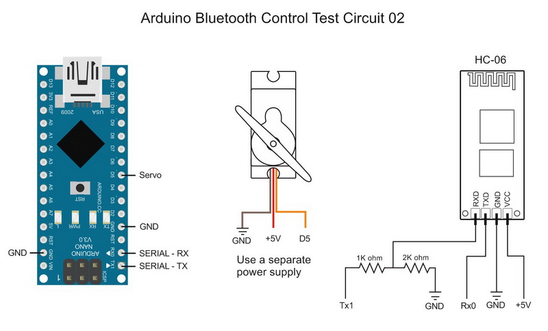
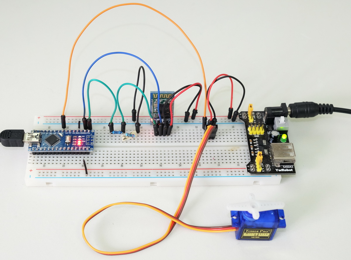
This example has a single servo connected to pin D5. The servo is controlled by using a slider in the Android app.
The SoftwareSerial and Servo libraries use the same Arduino resources and do not play nice together, therefore, I am using hardware serial to talk to the Bluetooth module.
I am using a 5V breadboard power supply to power the servo and the Bluetooth module. The Arduino is powered from the USB, however, once programmed, the Arduino could take power from the breadboard power supply as well. All grounds are connected.
Test Sketch 02. Controlling a servo
The Initialization is just 2 commands:
Serial.print("<P05000170000>");// Initialize pin D5 for PWM. min=0, max=170, start val=0
Serial.print("<ND05Servo Pos>");// Set the name for D5 to Servo Pos
Initialize pin D5 as PWN. Min=0, max=170. Set the pin description to “ServoPos”.
Remember to set the number of commands count to 2:
Serial.print("<C2>");// number of commands not including itself.
Main Functions
Since I am only controlling a servo all we need to do it check to see if we have new commands and if we do move the servo.
recvWithStartEndMarkers() – this checks serial in and takes any data that is between the start and end markers (< and >) and places it in to the global variable receivedChars. Any data not within the markers is ignored.
processCommand() – this checks receivedChars and if it is a PWM command we move the servo accordingly. The PWN command has a 3 digit value in ascii format, for example “123”, and this is converted to a numeric value.
byte pin =((receivedChars[1]-48)*10)+ receivedChars[2]-48;// PWM pinif( receivedChars[0]=='P'){// convert the ascii value to a numeric value
byte val =((receivedChars[3]-48)*100)+((receivedChars[4]-48)*10)+(receivedChars[5]-48);
myservo.write(val);}
Sketch
Because this example uses the hardware serial we cannot upload the sketch while the Arduino is connected to the RX and TX pins. Remove the connections, upload the sketch, and then redo the connections.
/*
* Sketch: ArduinoSketch_ArduinoBluetoothControl_example002b_ServoControl
* By Martyn Currey
* 14.11.2015
* Written in Arduino IDE 1.6.3
*
* Requires the Arduino Bluetooth Control Android App.
*
* See http://www.martyncurrey.com/arduino-bluetooth-control/
*
* Control the position of a servo motor
* Uses hardware serial to talk to the Bluetooth module
* Software serial conflicts with the Servo library
*
* The example uses the following pins
* TX1 - hardware serial TX
* RX0 - hardware serial RX
* D5 - servo
*
* It is recommended not to power the servo from the Arduino.
*
*/#include <Servo.h>
Servo myservo;// create a servo object char rc =' ';const byte maxDataLength =20;char receivedChars[21];
boolean newData =false;void setup(){
myservo.attach(5);
myservo.write(0);// Use the LED on pin 13 to show status // Flashing means sending initialization commands and waiting for a reply// On means the Android app has replied correctly
pinMode(13, OUTPUT);
digitalWrite(13,LOW);// open serial connection to the bluetooth module
Serial.begin(9600);while(!Serial);// Send initialization commands and the wait for an "OK"
boolean LEDisON =false;
boolean done =false;
byte count =0;
boolean sendInitCodes =true;
newData =false;int refreshRate =250;unsignedlong startTime = millis();while(!done){// This bit flashes the LED on pin 13. if( millis()- startTime > refreshRate){
startTime = millis();if(LEDisON){ LEDisON =false; digitalWrite(13,LOW);}else{ LEDisON =true; digitalWrite(13,HIGH);}
count++;// if reply is not received within 3 seconds resend the commandsif(count==12){ count =0; sendInitCodes =true;}}// Keep sending the initialization commands until the "OK" reply is received.if(sendInitCodes ==true){
sendInitCodes =false;
Serial.print("<START>");// Start marker
Serial.print("<P05000170000>");// Initialize pin D5 for PWM. min=0, max=170, start val=0
Serial.print("<ND05Servo Pos>");// Set the name for D5 to Servo Pos
Serial.print("<C2>");// number of commands not including itself.
Serial.print("<END>");// End marker}
recvWithStartEndMarkers();// check for new data from the Bluetooth moduleif(newData){// The Android app receives the commands and sends an "OK" back.if((receivedChars[0]=='O')&(receivedChars[1]=='K')){ done =true;}else{newData =false;}}}// while (!done) // Turn on the built in LED to show the app has received the initialization codes
digitalWrite(13,HIGH);
newData =false;
receivedChars[0]='\0';}// void setup()void loop(){
recvWithStartEndMarkers();// check to see if we have received any new commandsif(newData){ processCommand();}// if we have a new command set the Arduino pin accordingly
delay(5);}/*
****************************************
* Function processCommand
* parses data commands contained in receivedChars[]
* receivedChars[] has not been checked for errors
*
* Passed:
*
* Returns
*
* Global:
* receivedChars[]
* newData
*
* Sets/Changes:
* newData
*
*/void processCommand(){
newData =false;
byte pin =((receivedChars[1]-48)*10)+ receivedChars[2]-48;// PWM pinif( receivedChars[0]=='P'){// convert the ascii value to a numeric value
byte val =((receivedChars[3]-48)*100)+((receivedChars[4]-48)*10)+(receivedChars[5]-48);
myservo.write(val);}}// function recvWithStartEndMarkers by Robin2 of the Arduino forums// See http://forum.arduino.cc/index.php?topic=288234.0/*
****************************************
* Function recvWithStartEndMarkers
* reads serial data and returns the content between a start marker and an end marker.
*
* Passed:
*
* Returns:
*
* Global:
* receivedChars[]
* newData
*
* Sets:
* newData
* receivedChars
*
*/void recvWithStartEndMarkers(){static boolean recvInProgress =false;static byte ndx =0;char startMarker ='<';char endMarker ='>';if(Serial.available()>0){
rc = Serial.read();if(recvInProgress ==true){if(rc != endMarker){
receivedChars[ndx]= rc;
ndx++;if(ndx > maxDataLength){ ndx = maxDataLength;}}else{
receivedChars[ndx]='\0';// terminate the string
recvInProgress =false;
ndx =0;
newData =true;}}elseif(rc == startMarker){ recvInProgress =true;}}}
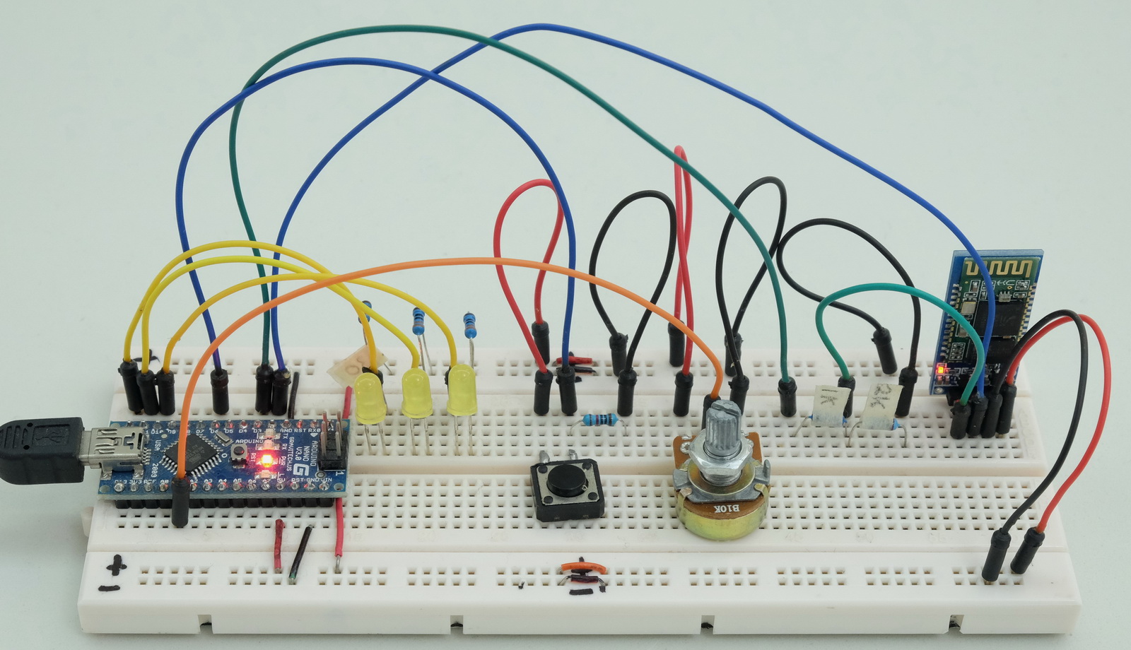
Example 3: 3 LEDs, 1 Push Button Switch. 1 Potentiometer
This is a more complex example that has: – 3 LEDs. – push button switch – potentiometer
It also uses the built in LED on pin D13.
All pins are given a descriptive name using the Name command.
The LEDs are controlled from the app; 2 are on/off and 1 is fade on / fade off. The state of the push button and the value of the potentiometer are shown in the app. The button switch can be either HIGH or LOW. The potentiometer value can be from 0 to 1023.
The LED on pin 13 is used to show the sketch status; blinking means sending initialization commands and waiting for the app to reply. Solid on means initialised and receiving/transmitting pin status data.
Pin D10, D11, and D12 have LEDs. The LEDs on pin D11 and D12 are on/off only. The LED on pin D10 is controlled via a PWM signal and fade in and out.
Pin D6 has a button switch attached. The status of the pin is checked and, if the value has changed, the value is sent to the Android app.
Pin A1 has a potentiometer attached, the pin is checked using analogRead() and the value sent to the Android app.
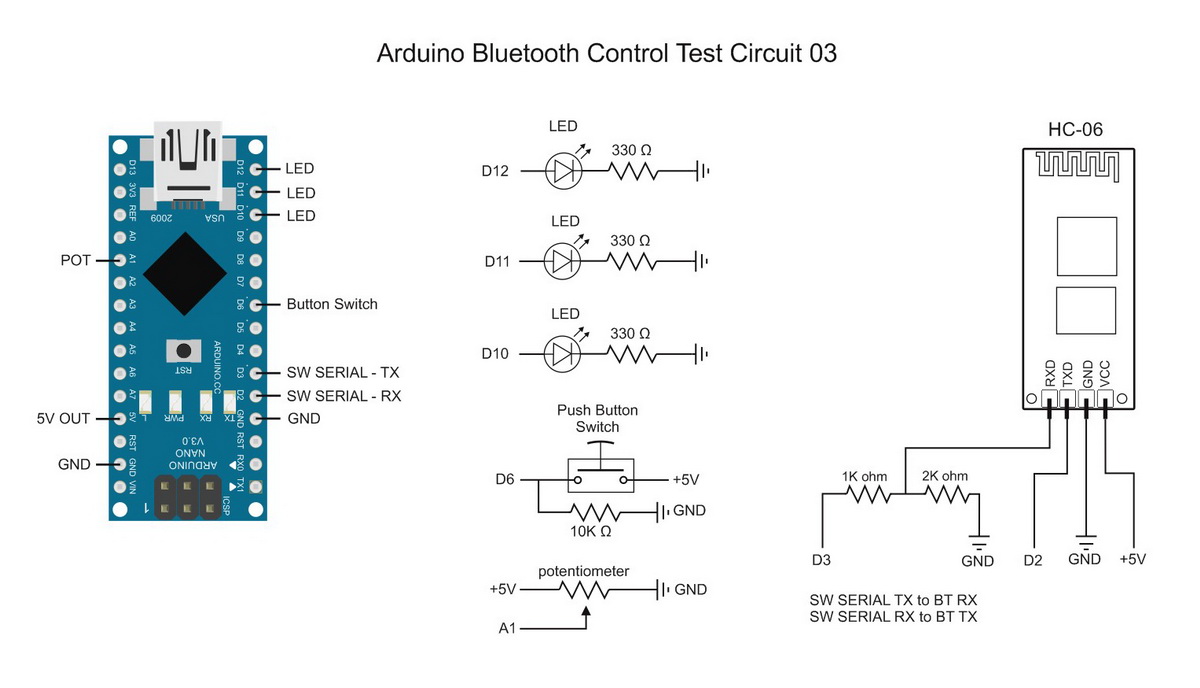
Test Circuit 03. 3 LEDs, Push Button Switch. Potentiometer
The bluetooth module is a HC-06 set for 9600 baud rate. You can use different baud rates if you wish. Match the baud rate in the sketch with the baud rate of your Bluetooth device. A HC-05 can be used as well.
Test Sketch 03. Controlling 3 LEDs. Monitoring a button switch and a potentiometer
Set the pin function Set the pins; the LED pins for output and D6 for input.
// set the button switch pin to input
pinMode(6, INPUT);// Set the LED pins to output and turn them off.
pinMode(12, OUTPUT);// Pin 12
pinMode(11, OUTPUT);// Pin 11
pinMode(10, OUTPUT);// Pin 10
digitalWrite(12,LOW);
digitalWrite(11,LOW);
digitalWrite(10,LOW);// potPin (A1) does not need initializing//Pin 13 LED is used to show status // Flashing means sending initialization commands and waiting for a reply// On means the Android app has replied correctly
pinMode(13, OUTPUT);
digitalWrite(13,LOW);
Initialization commands Initialize the pins:
BTserial.print("<START>");// Start marker
BTserial.print("<A010000>");// Initialize analogue pin A01. Start value 0
BTserial.print("<D06IL>");// Set D6 to input. Start value = LOW
BTserial.print("<P10000255000>");// Initialize D10 for PWN. Start value = 0
BTserial.print("<D11OL>");// set D11 to output. Start value = LOW
BTserial.print("<D12OL>");// set D12 to output. Start value = LOW
BTserial.print("<ND12LED #1>");// set the pin description for D12 to LED #1
BTserial.print("<ND11LED #2>");// set the pin description for D11 to LED #2
BTserial.print("<ND10LED Fader>");// set the pin description for D10 to LED Fader
BTserial.print("<ND06BTN Switch>");// set the pin description for D6 to BTN Switch
BTserial.print("<NA01Potentiometer>");// set the pin description for A1 to Potentiometer. This will be truncated
BTserial.print("<C10>");// number of commands not including itself.
BTserial.print("<END>");// End marker
Main Functions
checkPins() – this reads the input pins status and if changed sends the value out via software serial.
formatNumber – converts a numeric value to an ascii string
recvWithStartEndMarkers() – this checks the software serial in and takes any data that is between the start and end markers (< and >). Any data not within the markers is ignored. The received data is put in to the global variable receivedChars
processCommand() – this checks the received data and if the pin number matches the pin we are using (D12) it is set HIGH or LOW to turn the LED either on or off.
/*
* Sketch: ArduinoSketch_ArduinoBluetoothControl_example003b
* By Martyn Currey
* 01.07.2015
* Written in Arduino IDE 1.6.3
*
* Requires the Arduino Bluetooth Control Android App.
*
* See http://www.martyncurrey.com/arduino-bluetooth-control/
*
* Read pin states / values and send to an Android app over bluetooth
* Receive control commands from the Android app
* The Android app is initialized by commands sent from the Arduino
*
* The example uses the following pins
* A1 - a potentiometer
* D2 - software serial RX
* D3 - software serial TX
* D6 - button switch (pulled LOW)
* D10 - LED
* D11 - LED
* D12 - LED
*/// The Bluetooth module is connected to pin D2 and D3 and uses software serial#include <SoftwareSerial.h>
SoftwareSerial BTserial(2,3);// RX | TX// Change DEBUG to true to output debug information to the serial monitorconst boolean DEBUG =true;char numberString[10];// used to hold an ascii representation of a number// [10] allows for 9 digits but in this example I am only using 4 digitschar rc =' ';const byte maxDataLength =20;char receivedChars[21];
boolean newData =false;unsignedlong startTime =0;unsignedlong refreshRate =100;// I only send a value if the value has changed.// This means I need to store the old valueunsignedint oldPotVal =0;unsignedint newPotVal =0;
boolean oldButtonSwitchState =false;
boolean newButtonSwitchState =false;void setup(){// set the button switch pin to input
pinMode(6, INPUT);// Set the LED pins to output and turn them off.
pinMode(12, OUTPUT);// Pin 12
pinMode(11, OUTPUT);// Pin 11
pinMode(10, OUTPUT);// Pin 10
digitalWrite(12,LOW);
digitalWrite(11,LOW);
digitalWrite(10,LOW);// potPin (A1) does not need initializing//Pin 13 LED is used to show status // Flashing means sending initialization commands and waiting for a reply// On means the Android app has replied correctly
pinMode(13, OUTPUT);
digitalWrite(13,LOW);if(DEBUG){// open serial communication for debugging
Serial.begin(9600);
Serial.println("ArduinoSketch_ArduinoBluetoothControl_example003b");
Serial.println(" ");}// open software serial connection to the Bluetooth module
BTserial.begin(9600);// Send initialization commands and the wait for an "OK"
boolean LEDisON =false;
boolean done =false;
byte count =0;
boolean sendInitCodes =true;
newData =false;
refreshRate =500;
startTime = millis();while(!done){// This bit flashes the LED on pin 13. if( millis()-startTime > refreshRate){
startTime = millis();if(LEDisON){ LEDisON =false; digitalWrite(13,LOW);}else{ LEDisON =true; digitalWrite(13,HIGH);}
count++;// if reply is not received within 3 seconds resend the commandsif(count==6){ count =0; sendInitCodes =true;}}// Keep sending the initialization commands until the "OK" reply is received.if(sendInitCodes ==true){
sendInitCodes =false;
dumpBTserialBuffer();// not really required but it makes me feel better :-)
BTserial.print("<START>");// Start marker
BTserial.print("<A010000>");// Initialize analogue pin A01. Start value 0
BTserial.print("<D06IL>");// Set D6 to input. Start value = LOW
BTserial.print("<P10000255000>");// Initialize D10 for PWN. Start value = 0
BTserial.print("<D11OL>");// set D11 to output. Start value = LOW
BTserial.print("<D12OL>");// set D12 to output. Start value = LOW
BTserial.print("<ND12LED #1>");// set the pin description for D12 to LED #1
BTserial.print("<ND11LED #2>");// set the pin description for D11 to LED #2
BTserial.print("<ND10LED Fader>");// set the pin description for D10 to LED Fader
BTserial.print("<ND06BTN Switch>");// set the pin description for D6 to BTN Switch
BTserial.print("<NA01Potentiometer>");// set the pin description for A1 to Potentiometer. This will be truncated
BTserial.print("<C10>");// number of commands not including itself.
BTserial.print("<END>");// End markerif(DEBUG){ Serial.println("Sent init commands. Waiting for receipt");}}
recvWithStartEndMarkers();// check for new data from the Bluetooth moduleif(newData){// The Android app receives the commands and sends an "OK" back.if((receivedChars[0]=='O')&(receivedChars[1]=='K')){ done =true;}else{newData =false;}if(DEBUG){ Serial.print("receivedChars = "); Serial.println( receivedChars );}}}// while (!done) // Turn on the built in LED to show the app has received the initialization codes
digitalWrite(13,HIGH);if(DEBUG){ Serial.println("OK received from the app");}// refeshRate is the frequency to check the input pins
refreshRate =100;}// void setup()void loop(){if( millis()-refreshRate > startTime){
startTime = millis();
checkPins();// read the pin values and if the values have changed send the new values to the Android app}
recvWithStartEndMarkers();// check to see if we have received any new commandsif(newData){ processCommand();}// if we have a new command set the Arduino pin accordingly}/*
****************************************
* dumpBTserialBuffer
* removes data from the software serial buffer
*
* passed:
*
* global:
*
* Returns:
*
* Sets:
*
*/void dumpBTserialBuffer(){while(BTserial.available()>0){char t = BTserial.read();}}/*
****************************************
* Function processCommand
* parses data commands contained in receivedChars[]
* receivedChars[] has not been checked for errors
*
* passed:
*
* global:
* receivedChars[]
* newData
*
* Returns:
*
* Sets:
*
*/void processCommand(){
newData =false;
byte pin =((receivedChars[1]-48)*10)+ receivedChars[2]-48;// digital pin if( receivedChars[0]=='D'){if( receivedChars[3]=='H'){ digitalWrite(pin,HIGH);}if( receivedChars[3]=='L'){ digitalWrite(pin,LOW);}if(DEBUG){ Serial.print("Digital pin command = "); Serial.println(receivedChars);}}// PWM pinif( receivedChars[0]=='P'){
byte val =((receivedChars[3]-48)*100)+((receivedChars[4]-48)*10)+(receivedChars[5]-48);
analogWrite(pin, val);if(DEBUG){ Serial.print("PWN command = "); Serial.println(receivedChars);}}}/*
****************************************
* Function checkPins
* Checks the values of the deignated pins and if the value has changed sends ascii codes to software serial
*
* passed:
*
* global:
* newPotVal
* oldPotVal
* potPin
* newButtonSwitchState
* oldButtonSwitchState
* buttonSwitchPin
* numberString
*
* Returns:
*
* Sets:
*
*/void checkPins(){// Check the value on analogue pin A1
newPotVal = analogRead(A1);//The pot I am using jitters +/- 1 so I only using changes of 2 or more. if(abs(newPotVal-oldPotVal)>1){
oldPotVal = newPotVal;
formatNumber( newPotVal,4);
BTserial.print("[A01");
BTserial.print(numberString);
BTserial.print("]");if(DEBUG){ Serial.print("[A01"); Serial.print(numberString); Serial.println("]");}}// Check the state of pin 6 - the button switch.
newButtonSwitchState = digitalRead(6);if(newButtonSwitchState != oldButtonSwitchState){
oldButtonSwitchState = newButtonSwitchState;if(oldButtonSwitchState ==true){if(DEBUG){ Serial.println("[D06H]");}
BTserial.print("[D06H]");}else{if(DEBUG){ Serial.println("[D06L]");}
BTserial.print("[D06L]");}}}/*
****************************************
* Function formatNumber
* formats a number in to a string and copies it to the global char array numberString
* pads the start of the string with '0' characters
*
* passed:
* number = the integer to convert to a string
* digits = the number of digits to use
*
* global:
* numberString
*
* Returns:
*
* Sets:
* numberString
*
*/void formatNumber(unsignedint number, byte digits){char tempString[10]="\0";strcpy(numberString, tempString);// convert an integer into a acsii string base 10itoa(number, tempString,10);// create a string of '0' characters to pad the number
byte numZeros = digits -strlen(tempString);if(numZeros >0){for(int i=1; i <= numZeros; i++){strcat(numberString,"0");}}strcat(numberString,tempString);}// function recvWithStartEndMarkers by Robin2 of the Arduino forums// See http://forum.arduino.cc/index.php?topic=288234.0/*
****************************************
* Function recvWithStartEndMarkers
* reads serial data and returns the content between a start marker and an end marker.
*
* passed:
*
* global:
* receivedChars[]
* newData
*
* Returns:
*
* Sets:
* newData
* receivedChars
*
*/void recvWithStartEndMarkers(){static boolean recvInProgress =false;static byte ndx =0;char startMarker ='<';char endMarker ='>';if(BTserial.available()>0){
rc = BTserial.read();if(recvInProgress ==true){if(rc != endMarker){
receivedChars[ndx]= rc;
ndx++;if(ndx > maxDataLength){ ndx = maxDataLength;}}else{
receivedChars[ndx]='\0';// terminate the string
recvInProgress =false;
ndx =0;
newData =true;}}elseif(rc == startMarker){ recvInProgress =true;}}}
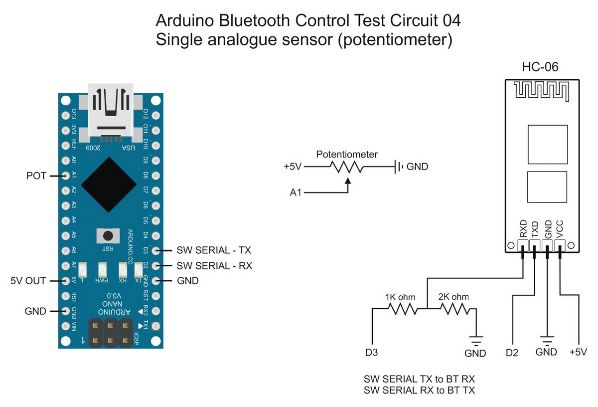
Example 04. Single Analogue Sensor (Potentiometer)
This is a basic example of using a single analogue sensor. For this example I am using a potentiometer but any other analogue sensor can be used. The potentiometer is connected to A1,
Test Sketch 04. Monitoring a a potentiometer
All this sketch does is read analogue pin A1 and send the value to the Android app. We are not receiving any data from the app and so we do not need to check.
Initialization commands
Set pin A1 for analogue and rename to “Potentiometer”
BTserial.print("<START>");// Start marker
BTserial.print("<A010000>");// Initialize analogue pin A01. Start value 0
BTserial.print("<NA01Potentiometer>");// set the pin description for A1 to Potentiometer. This will be truncated
BTserial.print("<C2>");// number of commands not including itself.
BTserial.print("<END>");// End marker
/*
* Sketch: ArduinoSketch_ArduinoBluetoothControl_example004b_Single_analogue_sensor
* By Martyn Currey
* 28.11.2015
* Written in Arduino IDE 1.6.3
*
* Requires the Arduino Bluetooth Control Android App.
*
* See http://www.martyncurrey.com/arduino-bluetooth-control/
*
* Read pin states / values and send to an Android app over bluetooth
* The Android app is initialized by commands sent from the Arduino
*
* The example uses the following pins
* A1 - potentiometer
*/// Change DEBUG to true to output debug information to the serial monitorconst boolean DEBUG =true;// The Bluetooth module is connected to pin D2 and D3 and uses software serial#include <SoftwareSerial.h>
SoftwareSerial BTserial(2,3);// RX | TXchar numberString[10];char rc =' ';const byte maxDataLength =20;char receivedChars[21];
boolean newData =false;unsignedlong startTime =0;unsignedlong refreshRate =2500;unsignedint oldAnalogueVal =0;unsignedint newAnalogueVal =0;void setup(){// A1 does not need initializingif(DEBUG){// open serial communication for debugging
Serial.begin(9600);while(!Serial){;}
Serial.println("ArduinoSketch_ArduinoBluetoothControl_example004b_Single_analogue_sensor");}// open software serial connection to the Bluetooth module
BTserial.begin(9600);if(DEBUG){ Serial.println("BTserial started at 9600");}
newData =false;
refreshRate =3000;// how often to send the init codes
boolean done =false;
startTime = millis();while(!done){if( millis()-startTime > refreshRate){
startTime = millis();
BTserial.print("<START>");// Start marker
BTserial.print("<A010000>");// Initialize analogue pin A01. Start value 0
BTserial.print("<NA01Potentiometer>");// set the pin description for A1 to Potentiometer. This may be truncated
BTserial.print("<C2>");// number of commands not including itself.
BTserial.print("<END>");// End markerif(DEBUG){ Serial.println("Sent init commands. Waiting for receipt");}}
recvWithStartEndMarkers();// check for new data from the Bluetooth moduleif(newData){if((receivedChars[0]=='O')&(receivedChars[1]=='K')){ done =true;}else{newData =false;}if(DEBUG){ Serial.print("receivedChars = "); Serial.println( receivedChars );}}}// while (!done) if(DEBUG){ Serial.println("OK received from the app");}// refeshRate is the frequency to check the input pin
refreshRate =500;
startTime = millis();}// void setup()void loop(){if( millis()-refreshRate > startTime){
startTime = millis();// Check the value on analogue pin A1
newAnalogueVal = analogRead(A1);if( newAnalogueVal != oldAnalogueVal ){
oldAnalogueVal = newAnalogueVal;
formatNumber( newAnalogueVal,4);
BTserial.print("[A01"); BTserial.print(numberString); BTserial.print("]");if(DEBUG){ Serial.print("[A01"); Serial.print(numberString); Serial.println("]");}}}}// loop()void formatNumber(unsignedint number, byte digits){char tempString[10]="\0";strcpy(numberString, tempString);// convert an integer into a acsii string base 10itoa(number, tempString,10);// create a string of '0' characters to pad the number
byte numZeros = digits -strlen(tempString);if(numZeros >0){for(int i=1; i <= numZeros; i++){strcat(numberString,"0");}}strcat(numberString,tempString);}// function recvWithStartEndMarkers by Robin2 of the Arduino forums// See http://forum.arduino.cc/index.php?topic=288234.0void recvWithStartEndMarkers(){static boolean recvInProgress =false;static byte ndx =0;char startMarker ='<';char endMarker ='>';if(BTserial.available()>0){
rc = BTserial.read();if(recvInProgress ==true){if(rc != endMarker){
receivedChars[ndx]= rc;
ndx++;if(ndx > maxDataLength){ ndx = maxDataLength;}}else{
receivedChars[ndx]='\0';// terminate the string
recvInProgress =false;
ndx =0;
newData =true;}}elseif(rc == startMarker){ recvInProgress =true;}}}
In version 3 of the app I added a <RESET> command. Here is a brief example on how to use it to have the Arduino automatically resend the initiazation commands when it detects the reset.
I am using the same circuit as example 4 – a single analogue sensor (potentiometer)
The main difference in the sketch is that the part that sends the initization commands has been moved to its own function. The means we can call it at anytime.
The varaible initialized is used to show whether or not we have sent the init commands and received a reply. When initialized is TRUE we know the Arduino has connected to the app and we can start to send and/or receive pin data.
We we receive the <RESET> command we simply set initialized to FALSE.
/*
* Sketch: ArduinoSketch_ArduinoBluetoothControl_RESET
* By Martyn Currey
* 13.02.2016
* Written in Arduino IDE 1.6.3
*
* Requires the Arduino Bluetooth Control Android App.
*
* See http://www.martyncurrey.com/arduino-bluetooth-control/
*
* Read pin states / values and sends to an Android app over bluetooth
* Receive control commands from the Android app
* The Android app is initialized by commands sent from the Arduino
*
* The example uses the following pins
* A1 - a potentiometer
* D2 - software serial RX
* D3 - software serial TX
*/// The Bluetooth module is connected to pin D2 and D3 and uses software serial#include <SoftwareSerial.h>
SoftwareSerial BTserial(2,3);// RX | TX// Change DEBUG to true to output debug information to the serial monitorconst boolean DEBUG =true;char numberString[10];// used to hold an ascii representation of a number// [10] allows for 9 digits but in this example I am only using 4 digitschar rc =' ';const byte maxDataLength =20;char receivedChars[21];
boolean newData =false;unsignedlong startTime =0;unsignedlong refreshRate =100;// I only send a value if the value of the sensor has changed.// This means I need to store the old value so I can compare.unsignedint oldPotVal =0;unsignedint newPotVal =0;
boolean initialized =false;void setup(){// potPin (A1) does not need initializing//Pin 13 LED is used to show status // Flashing means sending initialization commands and waiting for a reply// On means the Android app has replied correctly
pinMode(13, OUTPUT);
digitalWrite(13,LOW);if(DEBUG){// open serial communication for debugging
Serial.begin(9600);
Serial.println(__FILE__);
Serial.println(__DATE__);
Serial.println(" ");}
BTserial.begin(9600);// open software serial connection to the Bluetooth module
refreshRate =100;// refeshRate is the frequency to check the input pins}// void setup()void loop(){if(!initialized){
sendInitCommands();// send the init commands and wait for a reply.}else{if( millis()-refreshRate > startTime){
startTime = millis();
checkPins();// read the pin values and if the values have changed send the new values to the Android app}
recvWithStartEndMarkers();// check to see if we have received any new commandsif(newData){ processCommand();}// if we have a new command do something about it}}/*
****************************************
* Function sendInitCommands
* Sends initialization commands and then waits for a "OK" reply.
*
* passed:
*
* global:
* receivedChars[]
* newData
*
* Returns:
*
* Sets:
*
*/void sendInitCommands(){// Send initialization commands and the wait for an "OK"
boolean LEDisON =false;
boolean done =false;
byte count =0;
boolean sendInitCodes =true;
newData =false;longunsigned startTime = millis();while(!done){// This bit flashes the LED on pin 13. if( millis()-startTime >500){
startTime = millis();if(LEDisON){ LEDisON =false; digitalWrite(13,LOW);}else{ LEDisON =true; digitalWrite(13,HIGH);}
count++;// if reply is not received within 3 seconds resend the commandsif(count>=6){ count =0; sendInitCodes =true;}}// Keep sending the initialization commands until the "OK" reply is received.if(sendInitCodes ==true){
dumpBTserialBuffer();// not really required but it makes me feel better :-)
BTserial.print("<START>");// Start marker
BTserial.print("<A010000>");// Initialize analogue pin A01. Start value 0000
BTserial.print("<NA01Potentiometer>");// set the pin description for A1 to Potentiometer. This will be truncated
BTserial.print("<C2>");// number of commands not including itself
BTserial.print("<END>");// End marker
sendInitCodes =false;if(DEBUG){ Serial.println("Sent init commands. Waiting for reply");}}
recvWithStartEndMarkers();// check for new data from the Bluetooth moduleif(newData){// The Android app receives the commands and sends an "OK" back.if(strcmp("OK",receivedChars)==0){ done =true;}else{ newData =false;}if(DEBUG){ Serial.print("receivedChars = "); Serial.println( receivedChars );}}}// while (!done)
initialized =true;// Turn on the built in LED to show the app has received the initialization codes
digitalWrite(13,HIGH);if(DEBUG){ Serial.println("OK received from the app");}}/*
****************************************
* dumpBTserialBuffer
* removes data from the software serial buffer
*
* passed:
*
* global:
*
* Returns:
*
* Sets:
*
*/void dumpBTserialBuffer(){while(BTserial.available()>0){char t = BTserial.read();}}/*
****************************************
* Function processCommand
* parses data commands contained in receivedChars[]
* receivedChars[] has not been checked for errors
*
* passed:
*
* global:
* receivedChars[]
* newData
*
* Returns:
*
* Sets:
*
*/void processCommand(){
newData =false;if(strcmp("RESET",receivedChars)==0){
initialized =false;}if(strcmp("DISCONECT",receivedChars)==0){
initialized =false;}if(DEBUG){ Serial.print("Recieved data = "); Serial.println(receivedChars);}}/*
****************************************
* Function checkPins
* Checks the values of the deignated pins and if the value has changed sends ascii codes to software serial
*
* passed:
*
* global:
* newPotVal
* oldPotVal
* potPin
* newButtonSwitchState
* oldButtonSwitchState
* buttonSwitchPin
* numberString
*
* Returns:
*
* Sets:
*
*/void checkPins(){// Check the value on analogue pin A1
newPotVal = analogRead(A1);//The pot I am using jitters +/- 1 so I only using changes of 2 or more. if(abs(newPotVal-oldPotVal)>1){
oldPotVal = newPotVal;
formatNumber( newPotVal,4);
BTserial.print("[A01");
BTserial.print(numberString);
BTserial.print("]");if(DEBUG){ Serial.print("[A01"); Serial.print(numberString); Serial.println("]");}}}/*
****************************************
* Function formatNumber
* formats a number in to a string and copies it to the global char array numberString
* pads the start of the string with '0' characters
*
* passed:
* number = the integer to convert to a string
* digits = the number of digits to use
*
* global:
* numberString
*
* Returns:
*
* Sets:
* numberString
*
*/void formatNumber(unsignedint number, byte digits){char tempString[10]="\0";strcpy(numberString, tempString);// convert an integer into a acsii string base 10itoa(number, tempString,10);// create a string of '0' characters to pad the number
byte numZeros = digits -strlen(tempString);if(numZeros >0){for(int i=1; i <= numZeros; i++){strcat(numberString,"0");}}strcat(numberString,tempString);}// function recvWithStartEndMarkers by Robin2 of the Arduino forums// See http://forum.arduino.cc/index.php?topic=288234.0/*
****************************************
* Function recvWithStartEndMarkers
* reads serial data and returns the content between a start marker and an end marker.
*
* passed:
*
* global:
* receivedChars[]
* newData
*
* Returns:
*
* Sets:
* newData
* receivedChars
*
*/void recvWithStartEndMarkers(){static boolean recvInProgress =false;static byte ndx =0;char startMarker ='<';char endMarker ='>';if(BTserial.available()>0){
rc = BTserial.read();if(recvInProgress ==true){if(rc != endMarker){if(ndx < maxDataLength){
receivedChars[ndx]= rc;
ndx++;}}else{
receivedChars[ndx]='\0';// terminate the string
recvInProgress =false;
ndx =0;
newData =true;}}elseif(rc == startMarker){ recvInProgress =true;}}}

댓글 없음:
댓글 쓰기