BeagleBone Green
Introduction

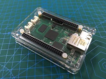
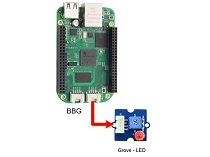
SeeedStudio BeagleBone Green (BBG) is a low cost, open-source, community supported development platform for developers and hobbyists. It is a joint effort by BeagleBoard.org and Seeed Studio. It is based on the classical open-source hardware design of BeagleBone Black and developed into this differentiated version. The BBG includes two Grove connectors, making it easier to connect to the large family of Grove sensors. The on-board HDMI is removed to make room for these Grove connectors.
Boot Linux in under 10 seconds and get started on development in less than 5 minutes with just a single USB cable.

Features
- Fully Compatible with BeagleBone Black
- Processor: AM335x 1GHz ARMR Cortex-A8
- 512MB DDR3 RAM
- 4GB 8-bit eMMC on-board flash storage
- 3D graphics accelerator
- NEON floating-point accelerator
- 2x PRU 32-bit microcontrollers
- Connectivity
- USB client for power & communications
- USB host
- Ethernet
- 2x 46 pin headers
- 2x Grove connectors (I2C and UART)
- Software Compatibility
- Debian
- Android
- Ubuntu
- Cloud9 IDE on Node.js w/ BoneScript library
- plus much more
Specification
| Item | Value |
|---|---|
| Processor | AM335x 1GHz ARMR Cortex-A8 |
| RAM | 512MB DDR3 |
| on-board Flash Storage | 4GB eMMC |
| CPU Supports | NEON floating-point & 3D graphics accelerator |
| Micro USB Supports | powering & communications |
| USB | Host 1 |
| Grove Connectors | 2 (One I2C and One UART) |
| GPIO | 2 x 46 pin headers |
| Ethernet | 1 |
| Operating Temperature | 0 ~ 75 |
Application Ideas
- Internet of Things
- Smart House
- Industrial
- Automation & Process Control
- Human Machine Interface
- Sensor Hub
- Robot
Here are some funny projects for your reference.
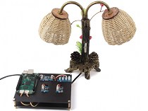
| Home Center | Retro Lamp | Drive a Motor |
|---|---|---|
 | 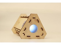 | 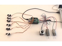 |
| MAKE IT NOW! | MAKE IT NOW! | MAKE IT NOW! |
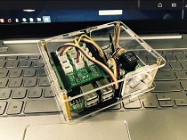
| BBG Acrylic Case | GPIO Control | Smart Light |
|---|---|---|
 |  |  |
| MAKE IT NOW! | MAKE IT NOW! | MAKE IT NOW! |
Hardware Overview
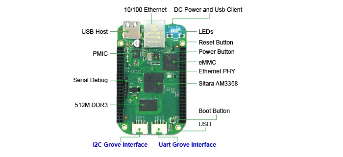
- USB Host - USB Host
- DC Power and USB Client - Power the board and act as client
- LEDs
- D2 is configured at boot to blink in a heartbeat pattern
- D3 is configured at boot to light during microSD card accesses
- D4 is configured at boot to light during CPU activity
- D5 is configured at boot to light during eMMC accesses
- Boot button
- When there’s a SD card insert, the system will boot from SD card first, if you want to boot from eMMC, press this button and then power on.
- Use as a normal button after boot, connect to GPIO_72
- I2C Grove Interface - Connected to I2C2
- Uart Grove Interface - Connected to UART2
- Serial Debug - Connect to UART0, PIN1~PIN6: GND, NC, NC, RX, TX, NC, note that pin1 is near to the USB.
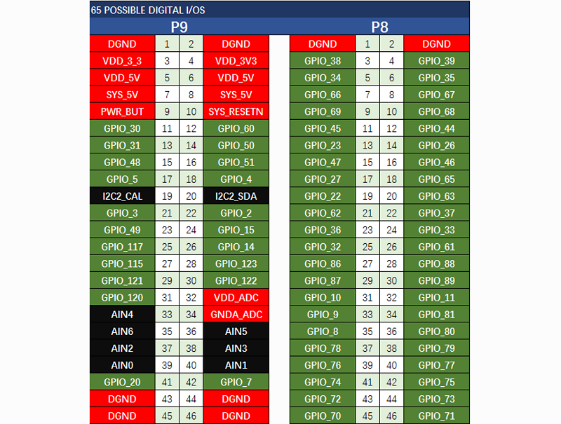
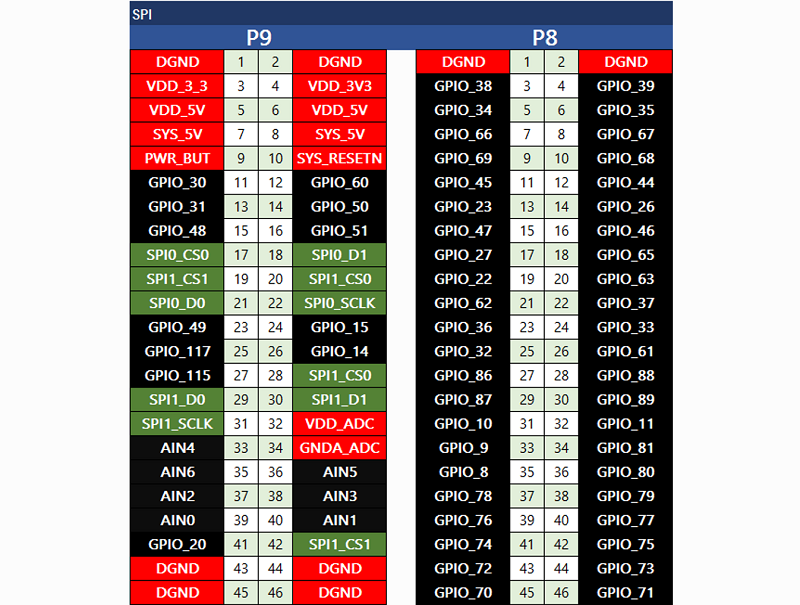
Pin map
Each digital I/O pin has 8 different modes that can be selected, including GPIO.
65 Possible Digital I/Os
Note
In GPIO mode, each digital I/O can produce interrupts.
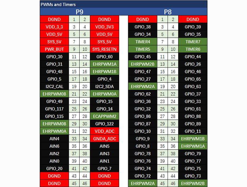
PWMs and Timers
Note
Up to 8 digital I/O pins can be configured with pulse-width modulators (PWM) to produce signals to control motors or create pseudo analog voltage levels, without taking up any extra CPU cycles.
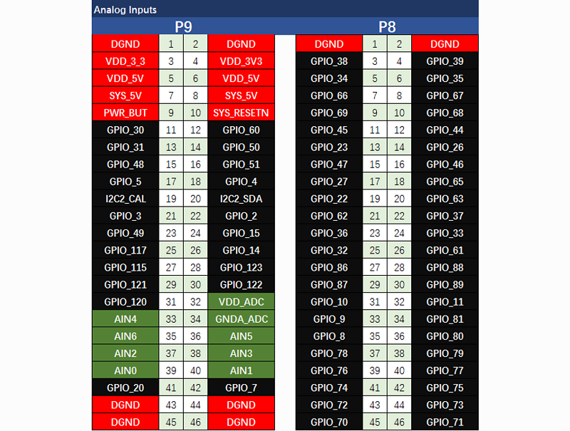
Analog Inputs
Note
Make sure you don’t input more than 1.8V to the analog input pins. This is a single 12-bit analog-to-digital converter with 8 channels, 7 of which are made available on the headers.
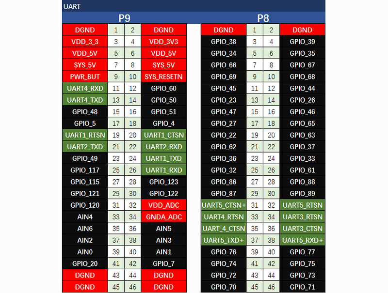
UART
Note
There is a dedicated header for getting to the UART0 pins and connecting a debug cable. Five additional serial ports are brought to the expansion headers, but one of them only has a single direction brought to the headers.
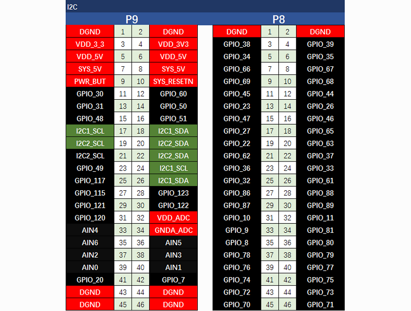
I2C
Note
The first I2C bus is utilized for reading EEPROMS on cape add-on boards and can’t be used for other digital I/O operations without interfering with that function, but you can still use it to add other I2C devices at available addresses. The second I2C bus is available for you to configure and use.
SPI
Note
For shifting out data fast, you might consider using one of the SPI ports.
Getting Started
Note
This chapter is writing under Win10. The steps are familiar for the other operate systems.
STEP1. Plug in your BBG via USB
Use the provided micro USB cable to plug your BBG into your computer. This will both power the board and provide a development interface. BBG will boot Linux from the on-board 2GB or 4GB eMMC.
BBG will operate as a flash drive providing you with a local copy of the documentation and drivers. Note that this interface may not be used to re-configure the microSD card with a new image, but may be used to update the boot parameters using the uEnv.txt file.
You’ll see the PWR LED lit steadily. Within 10 seconds, you should see the other LEDs blinking in their default configurations.
- D2 is configured at boot to blink in a heartbeat pattern
- D3 is configured at boot to light during microSD card accesses
- D4 is configured at boot to light during CPU activity
- D5 is configured at boot to light during eMMC accesses
STEP2. Install Drivers
Install the drivers for your operating system to give you network-over-USB access to your Beagle. Additional drivers give you serial access to your board.
| Operating System | USB Drivers | Comments |
|---|---|---|
| Windows (64-bit) | 64-bit installer | |
| Windows (32-bit) | 32-bit installer | |
| Mac OS X | Network Serial | Install both sets of drivers. |
| Linux | mkudevrule.sh | Driver installation isn’t required, but you might find a few udev rules helpful. |
Note
For Windows system, please note that:
- Windows Driver Certification warning may pop up two or three times. Click “Ignore”, “Install” or “Run”
- To check if you’re running 32 or 64-bit Windows see this.
- On systems without the latest service release, you may get an error (0xc000007b). In that case, please install and retry:
- You may need to reboot Windows.
- These drivers have been tested to work up to Windows 10
Note
Additional FTDI USB to serial/JTAG information and drivers are available from https://www.ftdichip.com/Drivers/VCP.htm.
Note
Additional USB to virtual Ethernet information and drivers are available from https://www.linux-usb.org/gadget/ and https://joshuawise.com/horndis.
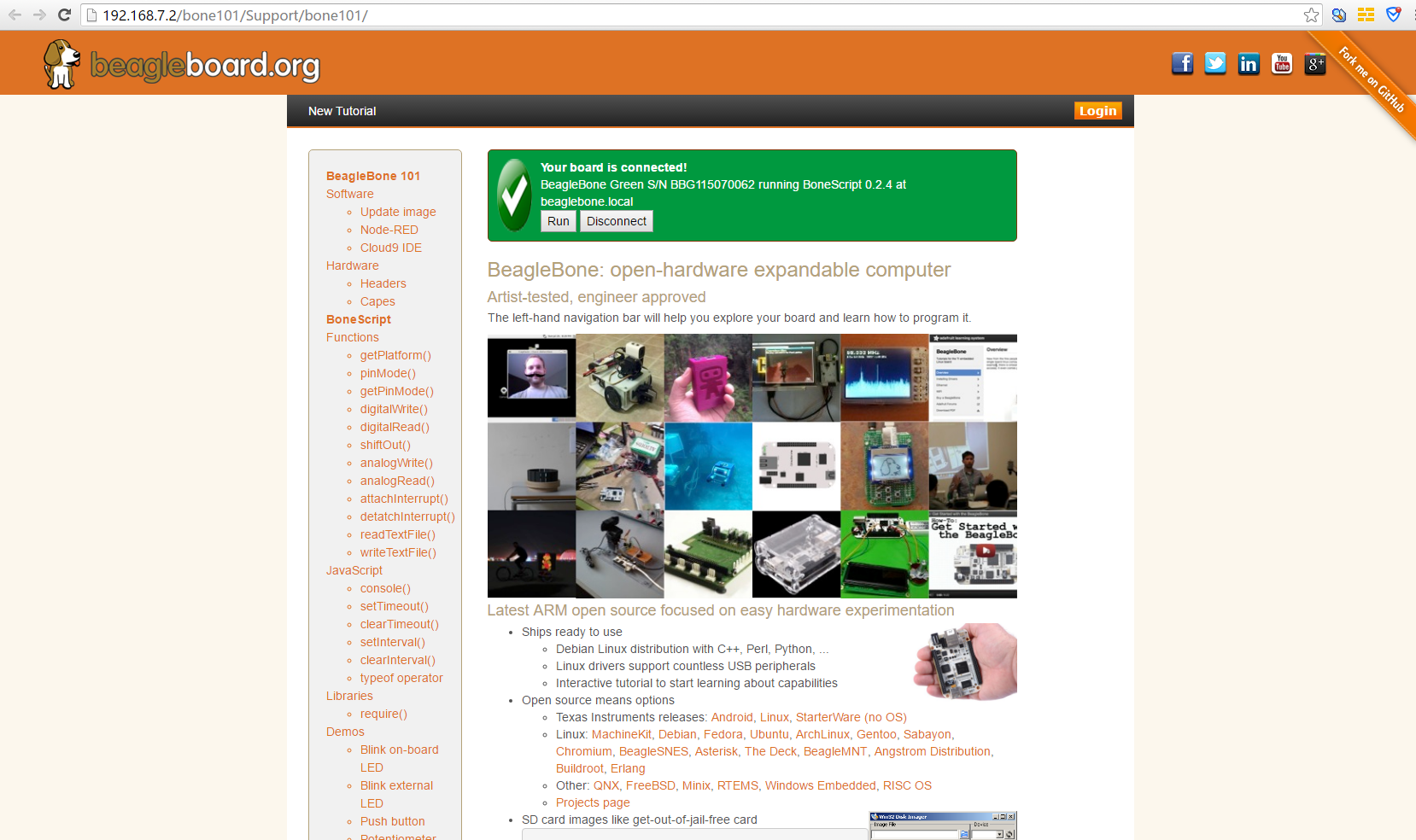
STEP3. Browse to your Beagle
Using either Chrome or Firefox (Internet Explorer will NOT work), browse to the web server running on your board. It will load a presentation showing you the capabilities of the board. Use the arrow keys on your keyboard to navigate the presentation.
Click http://192.168.7.2 to launch to your BBG. Older software images require you to EJECT the BEAGLE_BONE drive to start the network. With the latest software image, that step is no longer required.
STEP4. Cloud9 IDE
To begin editing programs that live on your board, you can use the Cloud9 IDE by click

Update to latest software
You need to update the board to latest software to keep a better performance, here we will show you how to make it step by step.
STEP1. Download the latest software image
First of all, you have to download the suitable image here.

Note
Due to sizing necessities, this download may take about 30 minutes or more.
The file you download will have an .img.xz extension. This is a compressed sector-by-sector image of the SD card.
STEP2. Install compression utility and decompress the image
Download and install 7-zip.
Note
Choose a version that suitable for your system.
Use 7-zip to decompress the SD card .img file
STEP3. Install SD card programming utility
Download and install Image Writer for Windows. Be sure to download the binary distribution.
STEP4. Write the image to your SD card
You need a SD adapter to connect your microSD card to your computer at the first. Then use the software Image Write for Windows to write the decompressed image to your SD card.
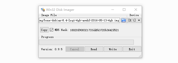
Click on Write button, then the process is started.
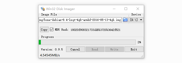
Note
- You may see a warning about damaging your device. This is fine to accept as long as you are pointing to your SD card for writing.
- You should not have your BeagleBone connected to your computer at this time.
- This process may need up to 10 minutes.
STEP5. Boot your board off of the SD card
Insert SD card into your (powered-down first) board. Then the board will boot from the SD card.
Note
If you don’t need to write the image to your on-board eMMC, you don’t need to read the last of this chapter. Otherwise pleas go ahead.
If you desire to write the image to your on-board eMMC, you need to launch to the board, and modify a file.
In /boot/uEnv.txt:
##enable BBB: eMMC Flasher:
#cmdline=init=/opt/scripts/tools/eMMC/init-eMMC-flasher-v3.sh
Change to:
##enable BBB: eMMC Flasher:
cmdline=init=/opt/scripts/tools/eMMC/init-eMMC-flasher-v3.sh
Then you will find the 4 user led light as below
Note
If you don’t find the upper tracing light, please press the RESET button to reset the board.
When the flashing is complete, all 4 USRx LEDs will be off. The latest Debian flasher images automatically power down the board upon completion. This can take up to 10 minutes. Power-down your board, remove the SD card and apply power again to be complete.
Grove for BBG
Grove is a modular, standardized connecter prototyping system. Grove takes a building block approach to assembling electronics. Compared to the jumper or solder based system, it is easier to connect, experiment and build and simplifies the learning system, but not to the point where it becomes dumbed down. Some of the other prototype systems out there takes the level down to building blocks. Good stuff to be learned that way, but the Grove system allows you to build real systems. It requires some learning and expertise to hook things up.
Below listed the Grove modules that work well with BBG.
| SKU | Name | Interface | link |
|---|---|---|---|
| 101020054 | Grove - 3-Axis Digital Accelerometer(+16g) | I2C | link |
| 101020071 | Grove - 3-Axis Digital Accelerometer(+400g) | I2C | link |
| 101020034 | Grove - 3-Axis Digital Compass | I2C | link |
| 101020050 | Grove - 3-Axis Digital Gyro | Analog | link |
| 101020081 | Grove - 6-Axis Accelerometer&Compass v2.0 | I2C | link |
| 101020072 | Grove - Barometer Sensor(BMP180) | I2C | link |
| 104030010 | Grove - Blue LED | I/O | link |
| 101020003 | Grove - Button | I/O | link |
| 111020000 | Grove - Button(P) | I/O | link |
| 107020000 | Grove - Buzzer | I/O | link |
| 104030006 | Grove - Chainable RGB LED | I2C | link |
| 101020030 | Grove - Digital Light Sensor | I2C | link |
| 103020024 | Grove - Finger-clip Heart Rate Sensor | I2C | link |
| 101020082 | Grove - Finger-clip Heart Rate Sensor with shell | I2C | link |
| 113020003 | Grove - GPS | UART | link |
| 104030007 | Grove - Green LED | I/O | link |
| 103020013 | Grove - I2C ADC | I2C | link |
| 103020006 | Grove - I2C Hub | I2C | link |
| 101020079 | Grove - IMU 10DOF | I2C | link |
| 101020080 | Grove - IMU 9DOF v2.0 | I2C | link |
| 101020040 | Grove - IR Distance Interrupter | I/O | link |
| 104030011 | Grove - OLED Display 0.96’‘ | I2C | link |
| 104030008 | Grove - OLED Display 1.12’‘ | I2C | link |
| 104030005 | Grove - Red LED | I/O | link |
| 103020005 | Grove - Relay | I/O | link |
| 316010005 | Grove - Servo | I/O | link |
| 101020023 | Grove - Sound Sensor | Analog | link |
| 101020004 | Grove - Switch(P) | I/O | link |
| 101020015 | Grove - Temperature Sensor | Analog | link |
| 101020019 | Grove - Temperature&Humidity Sensor Pro | Analog | link |
Cape for BBG
You will need some expansion board when you start a project. There’re many cape for BBG already, they include LCD display, motor driver as well as HDMI expansion etc. Below is some of them recommend.
| Grove Cape | Motor Bridge Cape | HDMI Cape |
|---|---|---|
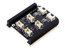 | 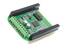 | 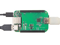 |
| GET ONE NOW! | GET ONE NOW! | GET ONE NOW! |
| Grove Cape | 5 Inch LCD | 7 Inch LCD |
|---|---|---|
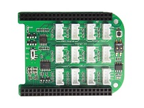 | 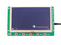 | 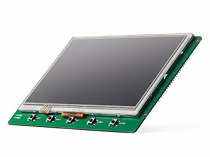 |
| GET ONE NOW! | GET ONE NOW! | GET ONE NOW! |
References
There’re many references to help you to get more information about the board.
- BeagleBoard Main Page
- BeagleBone Green info at BeagleBoard page
- BeagleBoard Getting Started
- Troubleshooting
- Hardware documentation
- Projects of BeagleBoard
- CE certification of BBG
- FCC certification of BBG
Resources
- BEAGLEBONE_GREEN SRM(v1a)(pdf)
- BEAGLEBONE_GREEN Schematic(pdf)
- BEAGLEBONE_GREEN Schematic(OrCAD)
- BEAGLEBONE_GREEN PCB(OrCAD)
Help us make it better
Thank you for choosing Seeed. A couple of months ago we initiated a project to improve our documentation system. What you are looking at now is the first edition of the new documentation system. Comparing to the old one, here is the progresses that we made:
- Replaced the old documentation system with a new one that was developed from Mkdocs, a more widely used and cooler tool to develop documentation system.
- Integrated the documentation system with our official website, now you can go to Bazaar and other section like Forum and Community more conveniently.
- Reviewed and rewrote documents for hundreds of products for the system’s first edition, and will continue migrate documents from old wiki to the new one.
An easy-to-use instruction is as important as the product itself. We are expecting this new system will improve your experience when using Seeed’s products. However since this is the first edition, there are still many things need to improve, if you have any suggestions or findings, you are most welcome to submit the amended version as our contributor or give us suggestions in the survey below, Please don’t forget to leave your email address so that we can reply.
Happy hacking
댓글 없음:
댓글 쓰기