Although I use a HC-06 in the below examples the HC-05 in slave mode can also be used.
Using MITs app inventor it is fairly easy to create an app that can turn a LED on and off from an Android device.
This is a fairly simply example of sending commands to the Arduino to turn a LED either on or off. The Android app sends ascii codes to the Arduino via the HC-06 BT module; “ON” for on and “OF” for off.
Load the app, connect to the HC-06 and then use the LED button to turn the LED on and off.
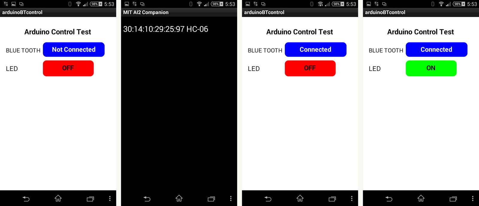
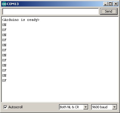
You can also open the serial monitor to see the commands as they are received

The steps involved are:
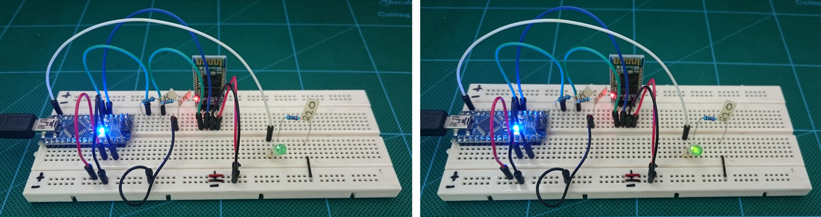
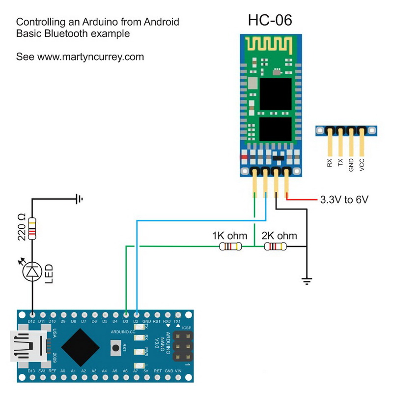
1. create a circuit that includes a Bluetooth module and a LED
2. create an Arduino sketch that can receive commands from the HC-06 and turn a LED on and off
3. create an Android app that sends commands over Bluetooth
1. create a circuit that includes a Bluetooth module and a LED
2. create an Arduino sketch that can receive commands from the HC-06 and turn a LED on and off
3. create an Android app that sends commands over Bluetooth
The circuit
The circuit is the same as the one used in Arduino and HC-06 (ZS-040) except the addition of a LED + resistor connected to pin D12. I used a 220 ohm resistor because that is what I had to hand but similar values will be OK.
Based on ohm’s law; using a source of 5V, a green LED with a forward voltage drop of 2.2v and a forward current of 20mA a 150 ohm resistor is recommended. So any value from 180ohm to around 680 ohms will be OK.

Arduino Sketch
The sketch receives data from the Bluetooth module via software serial. It then checks the data for “ON” and “OF” commands. When “ON” is received the LED is turned on and when “OF” is received the LED is turned off.
To ensure that data is received correctly the data is surrounded by start and end markers. This example uses “<" and ">“. I use the function recvWithStartEndMarkers which was posted on the Arduino forum by Robin2. I simply copied the function and did not need to change it.
The recvWithStartEndMarkers() function takes at the data received from the serial connection and copies anything it finds between the start and end markers to the receivedChars variable. When it has found something it sets the newData variable to true.
In the main loop we keep calling the recvWithStartEndMarkers() function until newData has been set. When newData is True we know we have a new command so we call parseData() to deal with it. Inside parseData() we reset newData to false and the process continues.
The full sketch:
Android App
I created the Android app in MITs app inventor. This was fairly easy once I had figured out how to use Bluetooth.
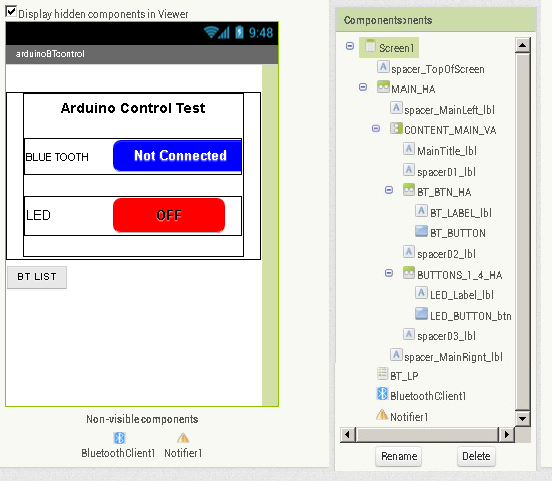
The app is very basic, it simply sends commands. There are no checks to see if the Arduino has actually received the commands or not. The screen is also very simple; it has a button for connecting to Bluetooth and a on/off button to control the LED. The app uses a ListPicker to store the available Bluetooth devices which is not displayed on screen. It is initiated from the connect button.
The app has 4 blocks and a list:

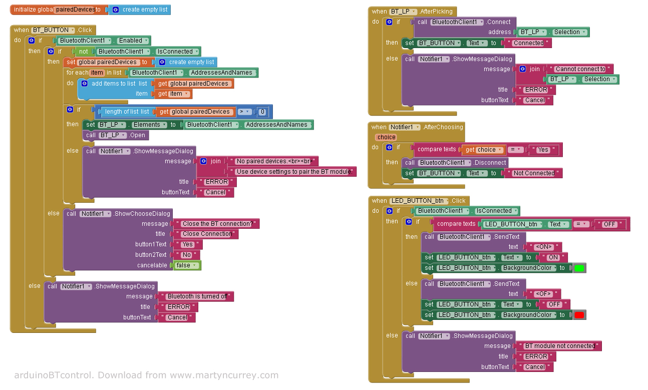
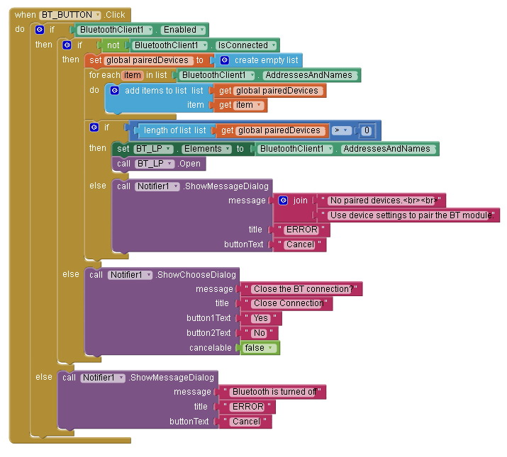
Block 1
This handles the connect button. When the button is clicked the block/function first checks to see if Bluetooth is enabled and then checks to see if there is already a Bluetooth connection. If Bluetooth is not turned on an error message is displayed. If there is already an active connection the user is asked if they would like to close it. The user reply is handled in Block3, Notifier1.AfterChoosing
If Bluetooth is on and there isn’t a current connection the paired Bluetooth devices are copied to the Bluetooth pairedDevices List. If the list has at least 1 item the contents of the list are copied to the ListPicker. The ListPicker is then activated to allow the user to select a Bluetooth device. I use the pairedDevices list so that I can count the number paired devices. I could not find a way of doing this when using just a ListPicker. If the list is empty an error message is displayed saying there are no paired devices.
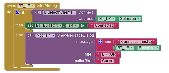
Block 2
Block 2, BT_LP.AfterPicking handles the List Picker after the user has selected one of the paired Bluetooth devices. It takes the selected item and tries to connect. If successful the text on the Bluetooth button is changed to “Connected”. If a connection cannot be established an error message is displayed.
Once a connection is established the app waits for the LED button to be pressed.
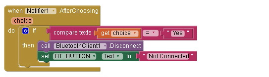
Block 3
Block 3 handles a Notifier dialogue that asks the user if they wish to close the connection

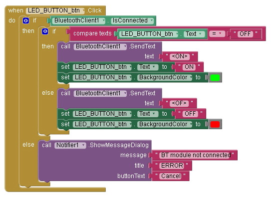
Block 4
Block 4, LED_BUTTON_btn.Click, handles the LED button. By checking the button text we can determine what command to send. If the text says “ON” then the LED is on and we need to turn it off so we send an “OF” command. If the text says “OFF”, the LED is off so we send an “ON” command to turn it on. The actual commands are “<ON>” and “<OF>”. The button text and background colour are updated to reflect the new LED status.
An error message is displayed if the LED button is clicked and there is no active connection.
Download
In part 2 we add 2-way communication and the facility to control the LED from the Arduino as well as the app.
Related:
Add an auto-connect function to an App Inventor app. Android MIT App Inventor – Auto Connect To Bluetooth
댓글 없음:
댓글 쓰기